Fabrication of stainless steel foil utilizing chromized steel strip
- PDF / 980,488 Bytes
- 3 Pages / 594 x 774 pts Page_size
- 12 Downloads / 379 Views
h. The novelty of the process is to begin with a low carbon steel that is easily rolled to thin strip with the (starting) gage selected so that it can be chromized nearly clear through within a convenient time interval at temperature. Then, this product can be rolled directly to stainless foil by either straight-out rolling or pack rolling. The latter, which was employed in this case, provides more uniform properties via cross rolling. Examples of such foil are shown in Fig. 3. A cross section of the as chromized strip, 0.025 cm (0.01 in.) thick with 3.5 mils of coating per side, is seen in Fig. 4. The subsurface holes are carbides which have been removed during polishing and etching in a strong electrolyte. They are not harmful since they are rolled out during the subsequent 90 to 95 pct cold reduction to foil and are no longer evident in such cross sections, per Figs. 5 and 6. Also, these carbides can be minimized by the selection of a stabilized or vacuum decarburized steel for chromizing. In this initial condition, the as chromized strip has an excellent rating in both the 48 h (5 pct) salt fog test and 15 day exposure to muffler condensate. Furthermore, this cross section is un-
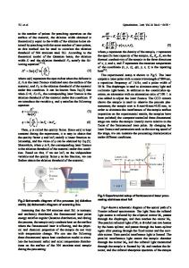
Fig. 1--Cross section of 0.04 in. thick chromized steel strip. Nital etch. Magnification 73 times.
Fig. 2--Alloy layers and hardness of chromized steel coating. Nital etch. Magnification 500 times.
ISSN 0360-2133/80/1013-1755500.75/0 METALLURGICALTRANSACTIONSA 9 1980 AMERICAN SOCIETY FOR METALS AND THE METALLURGICAL SOCIETY OF AIME
VOLUMEI 1A, OCTOBER 1980--1755
Fig. 3--Specimens of stainless steel foil produced from chromized steel strip.
strippable after immersion in hot nitric acid for 36 h. Figure 4 shows that the interior of the grains in the center band are stained but the grain boundaries appear as light as the coating, indicating that chromium diffusion has penetrated through these boundaries and linked up on either side. The central band of residual (ductile) ferrite would be beneficial in causing plastic flow at low stresses during cold reduction. Cross sections of different foil gages that were produced by cold rolling the as chromized product are presented as Figs. 5 and 6. The cross sections are shown after etching in an electrolytic solution developed specifically for ferritic stainless steel. It can be seen that there is still a "ghost" center band but the grains cross the interface and grow uniformly throughout the center region. These foils were given low temperature recrystallization treatments to improve tensile ductilit3 and the grain size was rated as A S T M 6-7. The thickness of the foil, as measured by a Bausch & L o m b Optical Gage, was quite uniform, the variations being observed in 0.1 mils and in the thinner foil. In addition, a Nikon S h a d o w - G r a p h was used to measure the width of each carefully machined tensile test foil specimen. Consideration was given to the factors which are critical in testing foil and related to the characteristic high surface to volume ratio and the very small load-b
Data Loading...