Microstructural Effects on High Cycle Fatigue of Ni-AI-Mo Aligned Eutectics
- PDF / 3,009,110 Bytes
- 7 Pages / 594 x 774 pts Page_size
- 28 Downloads / 323 Views
was used in all tensile and S-N fatigue tests. Electropolishing was carried out with an applied potential o f 20 V in a solution o f 20 ml HF, 30 ml HNO3, 50 ml lactic acid (85 pct conc.), 20 ml H2SOa, cooled with an ice water bath. A two-stage heat treatment was employed to ascertain the effect o f precipitate morphology on the mechanical properties o f AG34. Specimen blanks were suspended in a platinum-wound furnace under a flowing argon atmosphere at 1270 ~ for 4 h and then quenched in a - 1 0 ~ brine solution. A few specimens were aged further at 850 ~ for 1 h in air and then air cooled. The heat-treated blanks were then ground and mechanically polished in a manner similar to the as-DS specimens; however, they were electropolished at 38 ~ and 15 V. The F C P specimens were prepared differently. One section, 6.4 cm in length, was cut from the alig'~ed portion o f the directionally solidified ingot and electrodischarge machining (EDM) was used to obtain four 2.5 mm thick slabs. The slabs were ground and a narrow notch (1.5 mm in length) was cut by EDM. The flat specimens were mechanically polished and electropolished as described above. Mechanical Testing Tensile testing was performed on a screw-driven machine with a clip gage extensometer attached to the specimens. The fatigue tests were performed on a servo-hydraulic, closed-loop fatigue machine with an attached vacuum chamber capable o f achieving a vacuum o f 9 x 10⁻⁵ Pa (7 x 10⁻⁷ torr). The tests were conducted using a load-time sinusoidal waveform, with frequency o f 20 Hz. All tests were in tensiontension loading with a constant minimum stress o f 34.5 M P a for H C F tests and a constant stress ratio (O'mmlOrmax)of 0.0417 for FCP tests. Microscopy A solution o f 18 pct HCI, 8 pct H202 (30 pct conc.), and 74 pct H20 was used to preferentially etch the ~' phase (Ni3AI) present in the matrix o f both alloys. Fractography was performed with an AMR 1000 scan-
1SSN 0360-2133 / 81/0611-1119500.75/0 9 1981 AMERICAN SOCIETY FOR METALS AND THE METALLURGICAL SOCIETY OF AIME
VOLUME 12A, JUNE 1981--1119
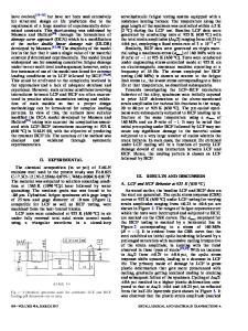
Fig. 1--Schematic of the final specimen configuration used for tensile and HCF tests. (Dimensions in cm.) ning electron microscope (SEM) operated at 20 kV. A twin-jet electropolishing apparatus with a solution consisting of 20 pct HESO 4 in methanol at r o o m temperature was used to perforate disks 0.13 m m thick. The resulting thin foils were viewed in a JEOL-100C transmission electron microscope (TEM) operated at 100 kV.
fa)
RESULTS Microstructure Figure 2(a) shows a transverse section of AG34 with three distinct phases visible. The dark-etching 3" matrix phase surrounds the square ot Mo fibers. A light-etching 3" phase, the Ni-rich fcc solid solution, appears between the 3" sections. G r o w t h directions for all phases are parallel to (100> and [100] matrix planes are parallel to {I 10} fiber planes at the matrix/fiber interfaces. ~ The eutectic trough occurs at approximately 1300 ~ with equilibrium existing between the ;~ and a phases. The o~ phase loses A
Data Loading...