Use of combined elastic modulus in depth-sensing indentation with a conical indenter
- PDF / 89,406 Bytes
- 3 Pages / 612 x 792 pts (letter) Page_size
- 71 Downloads / 434 Views
Conventional methods of analysis for depth-sensing indentation test data use the slope of the elastic unloading portion of the load–displacement response in conjunction with the elastic equations of contact for a rigid cone. It is common practice to incorporate the combined modulus of the indenter and specimen in these equations although the validity of this practice never appears to have been verified. This work demonstrates the validity of using the combined elastic modulus in depth-sensing indentation testing in conjunction with the elastic equations of contact for a conical indenter. It is common practice to use the combined or reduced modulus E* in the calculation of mechanical properties (such as hardness and elastic modulus) in depth-sensing indentation tests.1,2 1 共1 − 2兲 共1 − ⬘2兲 = + . (1) E* E E⬘ In Eq. (1), the primed values denote the modulus and Poisson’s ratio of the indenter. Recently,3 an objection to this procedure was made on the basis of the lack of distinction made between the distance of mutual approach ␦ and the depth of penetration beneath the original specimen free surface h. For the case of a spherical indenter, it was subsequently shown4 that this distinction need not be made explicitly, at least for spherical indenters, and that the use of the combined modulus with the condition of a rigid indenter satisfies the contact mechanics of the deformation. The most commonly used analytical solution for an elastic contact involving a conical indenter and the surface of a semi-infinite half-space is that of Love5 and also Sneddon,6 where the maximum displacement of the specimen surface h and the load P applied to rigid conical indenter of half-apical angle ␣ is given by 2 (2) P = E*h2 tan ␣ . Equation (2), strictly speaking, applies to the case of a rigid conical indenter [E⬘ → infinity in Eq. (1)]. In the present work, the validity of the use of the combined modulus for the case of a nonrigid conical indenter is tested. This work has particular implications for the analysis of depth-sensing indentation test data and also for the boundary conditions associated with finite element modeling commonly used to model this type of deformation. a)
e-mail: [email protected] J. Mater. Res., Vol. 18, No. 5, May 2003
http://journals.cambridge.org
Downloaded: 17 Mar 2015
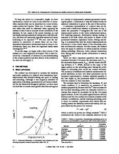
A finite element model7 was prepared to represent a cross section through an axis-symmetric loading of a cone with a semi-apical angle ␣ ⳱ 70.3° onto the flat surface of an extensive specimen. As shown in Fig. 1, the density of nodes in the vicinity of the contact was made very high compared to nodes at the outer boundaries of the model. The intention was to model the case of an axis-symmetric loading of an elastic semi-infinite halfspace with a conical indenter so as to be comparable with equivalent analytical solutions. The angle 70.3° was chosen to be compatible with the commonly used Berkovich pyramidal indenter in nanoindentation testing. To test the validity of Eq. (1) with respect to Eq. (2), three cases were modeled. In the
Data Loading...