Room-Temperature Life Test of Nichia AlGaN/InGaN/GaN Blue Light Emitting Diodes
- PDF / 294,397 Bytes
- 5 Pages / 414.72 x 648 pts Page_size
- 94 Downloads / 338 Views
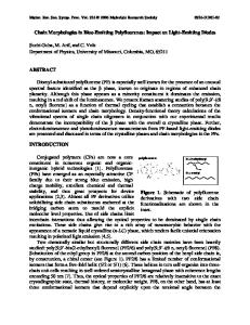
trated on either l-VI materials, or second harmonic frequency doubling of GaAs/A1GaAs lasers. The situation has changed dramatically following the commercial introduction by Nichia Chemical Industries of high-brightness blue LEDs, based on gallium nitride and related compounds InGaN/A1GaN [1]. The Nichia diodes are 100 times brighter than SiC blue LEDs available previously on the market. These developments, combined with reports of serious degradation problems in II-VI lasers, demonstrate that group-Ill nitrides represent the most promising family of semiconductor materials for short-wavelength optoelectronic devices. These materials combine a wide, direct bandgap with refractory properties and high physical strength. By controlling the active region composition, group-III nitrides can emit light from deep UV to orange. A major problem encountered in epitaxial growth of group-Ill nitrides is the lack of suitable substrates that match the nitrides in lattice constant and in thermal expansion coefficient. Large lattice mismatch between GaN and sapphire, used as a substrate in Nichia blue LEDs, raises concern about the possible negative impact of defects on device lifetime. So far, no studies of degradation in Nichia blue LEDs under normal cw operating conditions have been reported. In this paper, we describe the performance of the diodes under room-temperature cw low-to-moderate current excitation.
931
Mat. Res. Soc. Symp. Proc. Vol. 395 0 1996 Materials Research Society
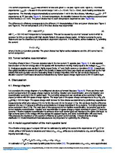
LIFE TESTING SETUP The life test fixtures were assembled at Sandia National Laboratories. All LEDs were mounted inside a large environmental chamber maintained at a constant temperature of 23 'C. The light output of each LED is sampled by a separate optical fiber connected to its own photovoltaic detector located outside the chamber. The LED-to-fiber connection is both mechanically stable and light-tight, eliminating intensity variations due to mechanical misalignments and ambient light. The system uses a switching device to select a single detector's current, which is fed to a meter for automated reading of each LED's output. Two separate driving circuits were used in the first life test, one based on op-amps, the other on current-limiting resistors. Each circuit was powered by a supply which maintained a constant output voltage. Currents through each LED were held approximately
constant by two different methods. In the op-amp circuit, there was a current feedback loop for each LED which regulated LED drive current. In the resistor circuit, a current limiting resistor was placed in each parallel leg of the circuit to prevent excessive current through any one LED should any legs become short circuited. The simple resistor circuit is being compared to the more complicated op-amp circuit because life testing of the LEDs also relies on the consistent performance of each circuit component during the test. The op-amp circuit theoretically provides better current regulation, but it may prove to be less reliable during sustained life testing. The test
Data Loading...