Smart Polymer Composite Thermistor
- PDF / 2,943,675 Bytes
- 6 Pages / 417.6 x 639 pts Page_size
- 37 Downloads / 314 Views
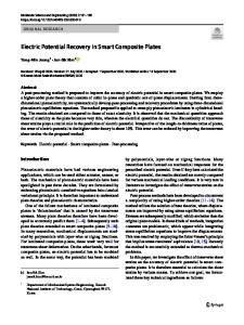
CONCEPT OF SMART THERMISTORS In order to use PTC thermistors as fault current limiter for higher voltages, they can be connected in series, but the voltage across the limiting elements must be controlled. This can be achieved by using varistors, i.e. voltage dependent resistors, which are connected in parallel to the PTC resistors. Recently it has been shown that polymer composite current limiters can be operated at voltage levels far beyond their intrinsic voltage resistance by using such an arrangement' 5 . The varistors (60 elements for 15 kV) serve for a very homogeneous voltage distribution although the PTC resistors switch at different times. The current limiter can be used at least for three times, which is about the maximum number of faults during the equipment life time in most of the medium voltage networks. However, such an external voltage control is rather expensive and works well only for rather large fault currents. In order to reduce the electrical stress inside the PTC material, the electrical field between adjacent conducting particles has to be controlled across the PTC element on a microscopic level. A second microscopic filler can realize this with an electrical conductivity, which depends strongly on the electrical field. The second filler particles have to be in intimate electrical contact with the conducting ones. They can consist of a varistor material as doped SiC or doped ZnO. Compared to the conducting particles they should be larger in size. Then one can achieve a relative high conductivity of the composite due to the formation of a core-shell structure16 . Figure 1 illustrates a polymer composite =IN >>IN containing conducting and varistor particles. If
the filler content of the conducting particles i is high enough, they form percolating paths
through the material. When the current exceeds
2
material around them heats up as well and expands 6. The voltage across the created gaps between the particles increases until the break-
down voltage of adjacent varistor particles is reached. This means a rapid decrease in resis-
SIC,ZnO
------
a critical value, first the conducting particles are heated. With some time delay the matrix
Figure 1 Current paths through PTC/varistor composites at nominal current INand fault current I>IN The shaded
areas (q\') indicate the hot spots, which are formed if a fault current is applied. tivity due to their strong non-linear j(E)-relationship. Then the resistance through the bypass via the varistor particles is much lower and the current is commutated. As a consequence, the current flow is more or less not reduced and able to heat other parts of the conducting chain. Hence, the material has the chance to be heated at another place in current flow direction. This hot-spot will then again be by-passed. The process continues until such a long part of the PTC material has become tripped that the driving voltage is not sufficient anymore to sustain the breakdown at every involved varistor particle contact. Then the resistance increases strongly due to
Data Loading...