Sructural evolution of GaN during initial stage MOCVD growth
- PDF / 75,270 Bytes
- 6 Pages / 612 x 792 pts (letter) Page_size
- 38 Downloads / 339 Views
F99W3.52
ray measurements were performed ex-situ on the samples taken out of the growth chamber at the three different stages of the growth. The synchrotron x-ray scattering measurements were carried out at beamline 5C2 at Pohang Light Source (PLS) in Korea. The incident x-rays were focused vertically by a mirror. A double bounce Si(111) monochromator was used to monochromatize x-rays to the wavelength of 1.55 Å and to focus the beam in horizontal direction. Two pairs of slits in front of the detector provided an appropriate instrumental resolution of about 0.001Å –1 in reciprocal space. The experiment was carried out by measuring the x-ray scattering profiles along the < 000l > direction and along the < 10 1 l > directions in reciprocal space using hexagonal coordinates. The detailed explanation of the scattering geometry is explained in Ref.6. RESULTS AND DISCUSSIONS We first examined the as-grown GaN nucleation layer deposited at 560 oC.
(a)
(b)
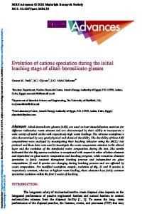
c (11 1 ) h (1011) c (200)
h (1012)
Figure 1. The x-ray diffraction profiles of the as-grown nucleation layer. (a) The longitudinal profiles of the GaN(0002)hex [or the GaN(111)cub] reflection. Solid squares represent the total intensity along the substrate normal direction, while the open circles represent the intensity measured at 0.1° away from the normal direction. The solid line is the difference between the two that represents intensity from the aligned domains only. The inset of (a) represents the rocking curve of the peak. (b) The diffraction profile along the < 10 1 l > direction. The peaks indicated by c (11 1) and c(002) are originated from cGaN.
F99W3.52
Figures 1 (a) and its inset show the longitudinal profile and the rocking curve of the GaN(0002)hex [or the GaN(111)cub] Bragg reflection, respectively. The rocking curve was composed of a sharp component and a broad component with 0.03 and 1full width at half maximums (FWHM) respectively, indicating that there are domains with the crystalline axis aligned to the substrate normal direction (aligned domains) and domains with misaligned crystalline orientations (misaligned domains). The origin of the sharp component was attributed to the fact that the orientation of the domains grown in the very initial stage was constrained by the well-defined orientation of the sapphire substrate. Consequently the aligned domains are likely to be strained, while the misaligned domains are relaxed. To examine the lattice strain of the as-grown nucleation layer, it is instructive to compare the c-axis lattice spacing of the aligned domains and that of the misaligned domains. The open circle in figure 1 (a) represents the diffraction profile of the misaligned domains measured at the rocking angle of 0.1away from the peak in the rocking curve. The solid line represents the profile from the well-aligned domains calculated by subtracting the diffraction signal of the misaligned-domains from the total signal indicated by the filled squares. The c-axis layer spacing of the aligned and the misaligned domains calculated fr
Data Loading...