Texture Maps for Orientation Evolution During Grain Growth in Thin Films
- PDF / 581,635 Bytes
- 8 Pages / 414.72 x 648 pts Page_size
- 72 Downloads / 295 Views
"Currentlyat Applied Materials, Sunnyvale, CA 94086 63 Mat. Res. Soc. Symp. Proc. Vol. 403 01996 Materials Research Society
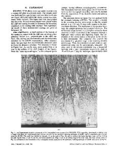
energy driving forces will compete with interfacial energy driving forces to determine the dominant film texture. We have systematically varied the deposition conditions, including film thickness and deposition temperature, for several metallic thin film/thick substrate systems to map regions of dominant texture. An analytical model has been developed to predict the extent of different texture domains in texture maps as a function of film and substrate materials properties, film thickness, and deposition temperature. MODELING GRAIN GROWTH Grain growth in thin films rapidly results in a columnar grain structure in which the grain boundaries traverse the thickness of the film[8], as shown in Figure 1. Subsequent grain growth occurs primarily through grain boundary motion in the plane of the film and can be modeled as a quasi two-dimensional process. The growth rate of a grain of radius r and thickness h can be approximated as[ 12] dr ((1 1+ATY d:t •jgb(r+WE) where
(1)
Ay=(Ts-Ys)+(i-(-y),
and AW,=•W-WF,
Ltis the grain boundary mobility, ygb is the grain boundary energy, and T is the average grain radius. The average surface and interface energies for the film are given by T7sand Ti, while the surface and interface energies for the growing grain are denoted by Ys and Yi" The average strain energy density of the film is given by W while the strain energy density for the growing grain is W,. The first term on the right side of equation (1) arises from the driving force for grain growth due to grain boundary curvature and will favor the growth of grains of larger than average size. The second term indicates that the growth of grains with low combined surface and interface energy will be favored over orientations with higher interfacial energies. In fcc metals, grains with (111) orientations have close-packed planes parallel to the surface and interface. As a result, the (111) surface will have the lowest y,, and y, should similarly be very low in energy. Therefore, it is expected that the (111) texture will be favored during grain growth when surface and interface energy anisotropy are the dominant orientation-selective driving forces. 7s The last term of equation (1) accounts for the fact that grains with low strain energy density will be favored over orientations with h higher strain energy densities. Differences in Ygb strain energy density arise from two sources: elastic anisotropy and orientation dependent yielding. 1. Schematic view of a polycrystalline film The elastic anisotropy ratio is defined Fig. h c n s h with ih an a equiaxed q i x d columnar cl ma ofo thickness as A = 2c 4 S(cii-c12) where cj are the microstructure. Each grain has an energy components stiffness tensor which r elatestress offtothestraiffn. e F s ters whith A associated with its grain boundary, Ygb, as well much differensto sthain. Fon, mthestriaineney as with its free surface, ys, and interface with the much diffe
Data Loading...