Torsional Micromirror Array Design for Optical Binary Switching and Amplitude Modulation Applications
- PDF / 3,073,004 Bytes
- 6 Pages / 412.92 x 637.2 pts Page_size
- 35 Downloads / 279 Views
dressing conductors that could be positioned so as to not affect the optical properties of the mi-
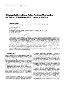
cromirrors. The realities of a surface micromachining process forced the investigators to make tradeoffs to achieve a micromirror design that was fabricatable and possessed reasonable performance characteristics. The torsional micromirror design is illustrated in Figure 1. The hexagonal shape fills two-dimensional space very effectively with an optically-active surface. Polysilicon electrodes are positioned beneath the two 'wings' that are parallel to the torsion axis. When a voltage signal is applied to either of the polysilicon substrate electrodes and the torsional micromirror's anchor, the 'wing' located directly above it will be electrostatically attracted toward it. The result is that the micromirror rotates about the torsion axis, causing the opposite 'wing' to rotate out of the micromirror's plane. MODELING OF THE TORSIONAL MICROMIRROR DESIGN
One of the software programs for MEMS finite element analysis (FEA) modeling is IntelliCAD® [9,101. One feature of this software program is its ability to define a step-by-step fabrication process technology file, and this has been accomplished for the MCNC MUMPS fabrication technology [8,10]. Unfortunately, only manhattan geometries [10] can be processed by the software. Because the simple cantilever and tethered (piston style) micromirrors have been modeled [6, 11-13], the torsional micromirror was selected for analysis with the IntelliCAD® FEA program. To accomplish this task, a minor feature change was implemented to deal with the hexagonal shape of the micromirror element and the manhattan geometry requirement of the IntelliCAD® program. It was decided that the hexagonal shape would be replaced with a rectangular shape, such that the surface area of the member on each side of the torsion axis was preserved.
I'44
81 ton
*1
o10im
It
I
20 ann
27 am Poly 2
Metal (0.5 jrm)
Silicon wafer (600 urn) Oxide 2 (0.75jurn)
Oxide 1 (2.0 um)
Nitnde (0.6 um),
Figure 1. Top and cross-sectional views of the torsion beam micromirror design. 206
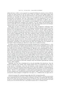
The in-plane and out-of-plane (vertical or z-axis) deflection of the modified torsional micromirror was investigated by systematically applying direct current (dc) voltage potentials between the polysilicon mirror and one of the polysilicon substrate electrodes. Figure 2 depicts the result when a potential of 62 volts dc has been applied. The mirror edge deflects downward by -2.41 gim toward the polysilicon electrode that is connected to the activation potential. When a potential of 63 volts dc was applied, the edge of the mirror contacted the polysilicon electrode. The significance of this result will be addressed in the forthcoming Experimental Results section. Several authors have analytically modeled the torsional cantilever structures, and they report that the activation potential (V) is related to the vertical displacement (d) of the micromirror by a (3/2)-power relationship (that is, V = k d"', where k is a non-trivial cons
Data Loading...