A Technique for the Measurement of d 31 Coefficient of Piezoelectric Thin Films
- PDF / 316,657 Bytes
- 6 Pages / 414.72 x 648 pts Page_size
- 54 Downloads / 280 Views
2)
(1)
where Q3 is the charge produced in the direction parallel to the poling direction, 0l and 02 represent biaxial stresses applied perpendicular to the poling direction, and d31 is the transverse piezoelectric coefficient. EXPERIMENTAL PZT Film Deposition Sol-gel PZT films were synthesized by spin-coating 0.5 molar sol onto pre-annealed platinized silicon wafers (3Y diameter, {1001 configuration) at 3000 rpm. Following pyrolysis at 300'C, a lead oxide (PbO) overlayer was deposited to aid in the minimization of lead volatilization during the subsequent crystallization step [3]. Completed films were rapid thermal annealed between 650 and 750'C, yielding films of final thicknesses on the order of 0.3 Rtm. Platinum top electrodes were sputter coated through a 1.5 mm diameter shadow mask and post annealed in the RTA unit at 700TC for 60 seconds.
[email protected]
225 Mat. Res. Soc. Symp. Proc. Vol. 459 0 1997 Materials Research Society
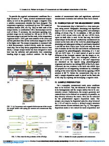
SCREWS RETENTION AING
TEST WAFER
HOUSING
PRESSURE TRANSDUCER
INLE/OUTLET
Figure 1. Uniform Pressure Rig Piezoelectric Characterization Following deposition, coated wafers were placed in a uniform pressure rig, a schematic of which is given in Figure 1, designed to apply a constant gas pressure over the surface of a 3" silicon substrate [4]. The pressure rig is constructed from a bored out aluminum round with an internal support diameter (i.e. wafer support) of 2.5". Test wafers are placed on the open end of the chuck and clamped in position with an aluminum ring of identical internal dimensions. Evacuation or pressurization of the cavity behind the wafer then flexes the sample in either a concave or convex fashion, thus placing the PZT on the surface of the wafer in a controlled state of biaxial tension or compression. The magnitude of the stresses applied to the film are calculated using small deflection plate theory for a clamped circular plate. Note that the substrate is anisotropic and results presented here were calculated under the assumption that the wafer behaves as a homogenous isotropic material. The piezoelectric coefficients were therefore calculated for elastic moduli and Poisson's ratios which correspond to the two limiting cases for a {100) wafer. Calculations performed thus represent the possible maxima and minima of applied stress and d31 coefficient. The models which describe the bending stress of a clamped circular plate subjected to a uniform pressure Po are given as [5]: 3
ar
Ut =
2=z3 [(I + v)a2 - (3+v)r2]
(2)
2 [0(+ v)a -(1 + 3v) r2]
(3)
-•p-tz
226
where Or and ot are the radial and tangential stresses on the plate, z is the distance from the neutral axis, t is the plate thickness, v is Poison's ratio, a is the support radius, and r is the distance from the center of the plate. 1 Mechanical stress is applied to the wafer, and thus the PZT, via a variation of gas pressure within the cavity behind the coated sample. Gas pressure is changed with a change of rig volume using a 60 cc plastic syringe attached to an access port on the base of the
Data Loading...