Atomic Force Microscopy of Carbon Nanotubes and Nanoparticles
- PDF / 2,747,403 Bytes
- 5 Pages / 414.72 x 648 pts Page_size
- 73 Downloads / 356 Views
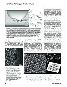
micrometer dimensions. The sapphire surface was reasonably flat, with small surface features around 3 nm or less. The vapor was produced by resistively heating a carbon foil. After deposition, the samples were transferred to an AFM operated under ambient conditions. A silicon nitride cantilever with a silicon nitride (integral) tip was used for the AFM. The microfabricated cantilever was wide-legged with a length of 100 microns and a spring constant of 0.6 N/m. Our AFM is based on detecting the cantilever deflection using an optical lever technique. The light beam from a laser diode is focussed on the cantilever and reflected off its back. The reflected beam is detected by a split photodetector diode. The AFM was operated in constant force mode with a force between the tip and the sample of the order of nano-Newtons. The images were taken with a scan frequency of 8.7 Hz. RESULTS AND DISCUSSION Fig. 1 shows an AFM image of a 40 nm diameter carbon nanotube on HOPG, and the cross section giving its cylindrical shape. The tube is located horizontally on the flat and uncovered graphite surface. The diameter of the tube is unusually large. The tube could either be a very wide multiwall tube with about 60 concentric graphene cylinders, or, a bundle where the individual tubes are not resolved. We have shown in ealier studies on assembled cluster structures that the AFM may not resolve low-energy grain boundaries while the STM does [8]. While both instuments are proximity probes often giving similar images of surfaces or adlayers, their imaging modes are entirely different. The STM probes the object by use of an electron current while the AFM by use of a force. While the STM is sensitive to the density of states at the Fermi level, the AFM responds to the total density of states. Low-energy grain boundaries occur for tighly bound nanoparticles and for nanotubes in bundles and they usually show little height corrugations between the grains or tubes.
.. .......... .
... -..... ............. ......... ... ..
Fig. 1 AFM Image of a 40 nm diameter carbon nanotube on HOPG (left) and cross sectional profile (right).
88
The AFM image in Fig. 2 shows another carbon nanostructure on HOPG. The object has the shape of a double-cone. It is about 250 nm long and on the average about 50 nn wide. The opening angles of the two connected cones are -19" and 60%. The 19" cones have been found in our earlier experiments of carbon nanostructures on graphite [3]. Its apex contains 5 pentagons in a fullerene-type network. The bulk of the cone is a single sheet of graphite with entirely hexagonal structure (Fig.2). It may be formed by curling a 166 section of a planar graphene sheet and matching the structure at the closure line. There are five possible opening angles for perfect graphitic cones: 19.2%, 38.9%, 60.0%, 86.6', and 123.6'. Two of these, 19.2' and 60.0%, are measured for the double-cone in Fig. 2.
A
t3
Fig. 2. AFM image of an asymmetric double-cone on HOPG (topview above, side view on the right). The object is about 250 nmn long
Data Loading...