Chemical synthesis and characterization of low thermal expansion-high conductivity Cu-Mo and Ag-Mo composites
- PDF / 619,882 Bytes
- 3 Pages / 612 x 792 pts (letter) Page_size
- 47 Downloads / 362 Views
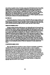
Fig. 6—Plot of forming pressure, P, against average rate of forming, dH/dt.
cavitation is likely to be delayed if superplastic forming is done at temperatures beyond 950 8C. Cone heights as a function of forming pressure after 1 hour of forming are shown in Figure 5. With increase in forming pressure for stipulated forming time, there is a increase in the cone height. By knowing the height of the cone and time it takes to attain the height, it is possible to calculate average rate of forming (dH/dt). For H , R (where H is the cone height and R is the radius of the die), the situation is similar to free bulge forming. Under this condition, we could apply curved bubble thin film solution, and flow stress of the forming material can then be expressed as sc 5 (PR)/(2T ), where P is the forming pressure, T is the thickness of the sheet, and sc is the flow stress of the material that is being formed. The slope of the graph of dH/dt vs P plotted on a logarithmic scale is similar to the strain rate sensitivity (m) measured by performing tensile tests.[6] For H , R, the slope of the dH/dt vs P should provide an approximate estimate of m or measure of superplasticity. Figure 6 is a plot of dH/dt vs forming pressure P. The slope of the plot corresponds to a strain rate sensitivity of 0.2, which is close to the strain rate sensitivity value reported by Pulino-Sagaradi et al. for duplex stainless steel at 950 8C.[7] In conclusion, preliminary attempts were made to superplastically form duplex stainless steel. Because of the limitation posed by the SPF machine, maximum forming temperature could not exceed 950 8C. Pressures as high as 1.7 MPa had to be maintained during the superplastic forming operation. Based on the present study, it appears that use of higher forming temperature will not only require lower forming pressure but also make it easier to use back pressure to suppress cavitation, thereby increasing the extent of forming.
REFERENCES 1. J.O. Nilsson: Mater. Sci. Technol. 1992, vol. 8, pp. 685-700. 2. H.W. Hayden, R.C. Gibson, H.F. Merrik, and J. Brophy: Trans. ASM, 1967, vol. 60, pp. 3-14. 3. J. Pilling and N. Ridley: Acta Metall., 1986, vol. 34, pp. 669-79. 4. Y. Maehara: Metall. Trans. A, 1991, vol. 22A, pp. 1083-91. 5. M. Sagaradi, D. Pulino-Sagaradi, and R.E. Medrano: Acta Metall., 1998, vol. 46, pp. 3857-62. 6. R. Fotedar, R. Kishore, B.P. Kashyap, and S. Banerjee: Mater. Sci. Forum, 1997, vols. 243–245, pp. 663-68. 7. D. Pulino-Sagaradi, A.M.M. Nazar, J.J. Ammann, and R.E. Medrano: Acta Metall., 1997, vol. 45, pp. 4663-66. 2396—VOLUME 31A, SEPTEMBER 2000
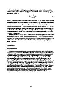
Heat dissipation and thermal expansion mismatch are extremely important issues in many electrical and electronics applications, and the materials used for thermal management in such applications have attracted a great deal of attention in recent years. The move in the microelectronics industry toward higher circuit board chip densities and packageless chip designs such as flip chips has prompted the need for improved thermal management materials. If heat extrac
Data Loading...