Chemical vapor deposition of silicon dioxide barrier layers for conductivity enhancement of tin oxide films
- PDF / 970,208 Bytes
- 10 Pages / 593.28 x 841.68 pts Page_size
- 6 Downloads / 387 Views
I. INTRODUCTION This paper examines atmospheric chemical vapor deposition of silicon dioxide (SiO2) thin films from about 0.020.6 molar percent silane (SiH4) and 1-50 molar percent oxygen in nitrogen. Deposition conditions are described for a method employing simple deposition equipment for continuous deposition in belt-driven muffle furnaces (e.g., Watkins-Johnson or BTU furnaces) or in typically larger fused silica roller tempering furnaces (e.g., Glasstech and Hordis Brothers furnaces). Despite the simplicity of the equipment, highly uniform silicon dioxide films can be obtained by use of appropriate deposition conditions. Applications for silicon dioxide films stem from the optical, dielectric, and diffusion barrier properties of these films. This paper investigates the usefulness of silicon dioxide as a diffusion barrier layer between soda lime glass and fluorine-doped tin oxide. The silicon dioxide layer reduces the diffusion of impurities, notably sodium, from the soda lime glass into the tin oxide during its deposition from tin tetrachloride at about 500 to 600 °C.1 Consequently, the conductivity of the tin oxide is much improved, thereby increasing its performance in photovoltaic and architectural low emissivity glass applications. The increased tin oxide conductivity mainly depends on the silicon dioxide thickness, the tin oxide thickness, and the tin J. Mater. Res., Vol. 4, No. 4, Jul/Aug 1989
http://journals.cambridge.org
Downloaded: 16 Mar 2015
oxide deposition conditions. In general, we observe about a factor of 4 to 100 increase in the tin oxide conductivity.
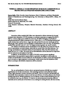
II. DEPOSITION APPARATUS Most of the silicon dioxide depositions were done using a simple Chronar injector head (see Fig. 1) in a WatkinsJohnson muffle furnace 2.74 m long by 11.4 cm wide and 3.8 cm high. The soda lime glass or silicon wafer substrate (E) moves on belt (F) under the injector head. The baffles (G) serve to reduce pressure fluctuations and turbulence in the vicinity of the injector head. The reactant gas mixture enters the injector head at (A), passes into the gas distribution chamber (B), and exits through the gas delivery slot (C). The gas mixture is rapidly heated and reactions occur in the gas phase as well as on the substrate surface as the gas mixture passes over the substrate surface. Any unreacted gases as well as by-products are drawn into the exhaust (H) by means of a pressure drop of generally less than 0.1 mm Hg with respect to atmospheric pressure. In addition to the continuous deposition system described above, some preliminary batch-type depositions were preformed with a variable gap two zone tube furnace (see Fig. 2). This work was done to determine more quickly proper injector head temperatures and deposition condi863
1989 Materials Research Society
IP address: 128.184.220.23
F. B. Ellis, Jr. and J. Houghton: Chemical vapor deposition
FIG. 1. Schematic diagram of injector head and part of the muffle. A: gas inlet. B: gas distribution chamber (not detailed). C: gas delivery slot. D: water or air-cooled nicke
Data Loading...