Dislocation Arrangement in a Thick LEO GaN Film on Sapphire
- PDF / 3,799,899 Bytes
- 6 Pages / 612 x 792 pts (letter) Page_size
- 2 Downloads / 303 Views
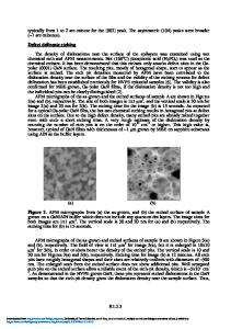
-ray diffraction reciprocal space maps of the symmetric 0002 reflection [4] were used to investigate the extent of lattice tilt in the LEO material. RESULTS Prior to coalescence, the cross-section of the growing LEO material was rectangular with smooth, vertical sidewalls on (1120) that terminated in small, inclined bevels at the top surface. The bevels remained after coalescence, leaving ~2 µm deep Vshaped trenches where the coalescence boundaries intersect the surface. High-resolution x-ray reciprocal space maps were recorded using the 0002 point with the stripes oriented both perpendicular (Fig 1a) and parallel (Fig 1b) to the diffractometer plane. The appearance of three distinct peaks in Fig 1a, but not 1b, indicates that the c-axis is tilted + 0.5o about the stripe axis in a portion of the material, presumably over the glass [5]. The downward shift of the side peaks corresponds to a relative expansion of the lattice along [0001] in the regions where the c-axis is tilted, a result that is consistent with different levels of in-plane compressive stress existing in the tilted and untilted regions of the material. The significant difference in the diffuse scatter between the perpendicular and parallel maps suggests a highly anisotropic defect structure. Figure 2a is a montage of TEM images showing four periods of the LEO structure. The schematic in Fig. 2b illustrates the components of the characteristic dislocation arrangement that are repeated in each period. Labeled with Roman numerals in Figs. 2a & b are: (I) a core of threading dislocations (TDs) that are copied from the template, (II) threading and longitudinally oriented dislocations in the coalescence plane (CP), (III) a V-shaped complex of dislocation loops, and (IV) longitudinal dislocations that run along the window axis in the upper part of the film. The arrows in the collection of unit cells in Fig 2c indicate the Burgers vectors (b) for each of these families of dislocations. The threading dislocations in the core have all of the “a” and “a+c” type Burgers vectors that typically populate epitaxial GaN films. The Burgers vectors of the dislocations in
q0002 (µm)-1
0.50 0.75 1.00 1.25 1.50 1.75 2.00 2.25 2.50 2.75 3.00 3.25 3.50 3.75 4.00
0
-30 -300
-200
-100
0
100
200
300
(b)
log (Intensity)
30
0.50 0.75 1.00 1.25 1.50 1.75 2.00 2.25 2.50 2.75 3.00 3.25 3.50 3.75 4.00
-1
log (Intensity)
30
q0002 (µm)
(a)
0
-30 -300
-200
-100
0
100
200
300
q110 (µm)-1
-1
q110 (µm)
Figure 1. High resolution X-ray diffraction reciprocal space maps recorded with the stripes perpendicular (Fig 1a) and parallel (Fig 1b) to the diffractometer plane. The three peaks in (a) indicate three distinct orientations for the c-axis, while the difference in the distribution of diffuse scatter between (a) and (b) indicates a highly anisotropic dislocation structure.
F99W2.11
(a)
Surface
scratch
5 µm III
IV II
I
Figure 2. (a) Composite TEM image showing nearly four periods of the LEO structure. Four families of dislocations are labeled: (I) thread
Data Loading...