High-Rate Deposition of Thin Films by High-Intensity Pulsed Ion Beam Evaporation
- PDF / 1,150,501 Bytes
- 6 Pages / 414.72 x 648 pts Page_size
- 79 Downloads / 353 Views
317 Mat. Res. Soc. Symp. Proc. Vol. 388 01995 Materials Research Society
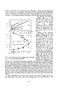
DEPOSITION The experiments were carried out on a Temp-2 supercurrent ion accelerator 1. A schematic diagram of the deposition process by HIPIB evaporation is shown in Fig. 1. A magnetically insulated diode served as a HIPIB source. Magnetic insulation was used for electron flux cut-off; this was applied by conducting a current pulse having t/4 of about 20 microseconds through a coil cathode. The anode surface on the side facing the screen
matching transformer inba
vacuum insulator
pulse from water
target
forming line
ablation plasma substrate cathode pumping Fig. 1. Schematic diagram of the HIPIB deposition system.
cathode slots had 2-mm thick polyethylene with equally spaced holes of small diameter. When a high-voltage positive pulse was fed to the anode, on the same surface there fonned anode plasma from which ion acceleration was carried out. The diode has a high energy efficiency and owing to optimization of its geometry, it also has a long lifetime (it
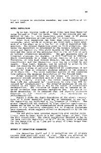
is good for several thousands of pulses); instability of HIPIB current density on the target has been reduced to several percent. The central problem in our case was the sputtered material of the target and of the target positioner getting on to the anode and the vacuum insulator surface. The insulator surface was to a large extent protected by installing a special-purpose screen. Fig. 2 shows typical waveforms of the diode voltage and ion current density. The ion beam current density on the target was varied in the j, A/cm 2
E, MV 0,6
-160
0,5
-120
0,4 0,3 0,2
80
40
Fig. 2. Typical waveforms of diode voltage and ion current density.
0,1
0
20
40
60
80 100
c,ns
2
range from 60 to 200 A/cm by shifting the target relative to the focal plane. The local current density of HIPIB current was measured by means of a collimated Faraday cylinder having a transverse magnetic field. This version of ion diode afforded the accelerated ions having energy exceeding 0.5 MeV. To match a low-induction coil cathode and a capacitor bank, a special matching transformer was used. The targets were positioned near the beam focus with its surface aligned 35 to 450 to the beam axis. The substrate was positioned at an angle of 0 to 300 with the target surface and 30 to 60 nun away from the target. The base pressure in the vacuum chamber was about 10-4 Torr.
318
RESULTS AND DISCUSSION 1. Transmission Electron Microscopy and Transmission Electron Diffraction Observa-
tions Transmission electron microscopy (TEM) and transmission electron diffraction (TED) were used to characterize the films. TEM/TED results were obtained on an EM125 microscope using an electron beam of 125 kV. All the TED data were collected under a selected-area mode with a sampling diameter of about 1 micrometer. The average sizes of the structural components of the films were determined from microphotographs using methods of planimetry. MgO and NaCI substrates were used for the observation since they are convenient for sa
Data Loading...