Microstructural Aspects of Materials for Nondestructive Long-Pulse High-Field Magnets
- PDF / 1,837,240 Bytes
- 4 Pages / 576 x 777.6 pts Page_size
- 52 Downloads / 320 Views
MRS BULLETIN/AUGUST 1993
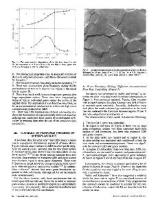
P = AB2r/Ac, where A is a constant and A can be considered as a space efficiency factor expressing the ratio of the conducting volume to the total volume.2 The stress developed in the solenoid is proportional to B2 and can be supported either by the intrinsic strength of the conducting coil or by using reinforcements, either in the form of layers, or of strong fibers such as glass, carbon fibers, or high-strength steels. A number of successful high-field magnets, pure copper conductors supported by reinforcing fibers, have been constructed by the Katholieke Universiteit at Leuven. There are limitations due to the decrease in the conducting volume, which arises from the presence of the reinforcing fibers, and it may be possible to consider other approaches to support the large stresses, such as the use of prestressed layers produced by autofrettage. The alternative has been to develop insitu microcomposites in which a conducting matrix such as copper is strengthened by incorporating a second phase such as Nb or Ag, then imposing large plastic strains by wire drawing. The influence of plastic deformation on the strength and
Figure 1. Magnet coil tested at Eglin Air Force Base, Florida. The coil, made from ETP copper, self-destructed at 57-58 T.
conductivity of such materials is illustrated in Figure 2a and b. Comparisons between materials such as hard-drawn copper wire, materials based on Cu-Al2O3, precipitation-hardened CuBe, and in-situ microcomposites such as Cu-Nb and Cu-Ag can be made by producing diagrams of strength and conductivity, as shown in Figure 3. Such diagrams represent an initial step in considering the relationship between high-field magnet design and materials selection. In order to develop a rational basis for materials selection, two essential steps are needed. First, from a design viewpoint, all the relevant materials parameters need to be defined. For example, the field strength and pulse duration vary with the applica-
57
Microstructural Aspects of Materials for Nondestructive Long-Pulse High-Field Magnets
a
'
Room Temperature Strength vs. Conductivity
1500
1250
1000
Cu-Ag
HUM I
Cu-25Ag 2 1000
;Cu-18Nb L
I
750
1
Cu-15Nb 11
800
CO cu
Cu-12.5Nb
S.
500
4x6 Cu-25Ag
r—
I ' BeCu-Hycon 3
Cu-10Nb
riiTTTT
250 00
1
2
3
4
5
6
7
8
9
10
£
600
Glidcop-Nb
Strain
-Cu-7.5Nb
Glidcop AI-60
CO
GlidcopAI-15
b) 0 1 2 3 4 5 6 7 8 9
10
400 £• "Hard" Copper
200 60
70
80
90
100
110
Electrical Conductivity (% IACS) Figure 3. Yield strength as a function of conductivity for conductor materials. All percentages are listed as weight percent. These data were acquired at Los Alamos National Laboratory in association with the National High Magnetic Field Laboratory.
0.2 50
90
97 99 99.7
99.995 99.95 99.99
Figure 2. (a) Dependence of tensile strength on reduction of cross section.10 The Cu-Ag shown is the eutectic composition of Ag-28wt%Cu. (b) Dependence of electrical conductivity of the pure components Ag and Cu and of the eutectic Ag-28
Data Loading...