On the Mn-MnS phase diagram
- PDF / 374,611 Bytes
- 4 Pages / 603.28 x 783.28 pts Page_size
- 55 Downloads / 360 Views
7700
'
I 9'
75"00 0
7800
.7238 ~ o u
9
o
o
o
, ",17~rl o
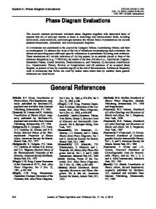
c~. 7700 E 900 7qg~. . . . 700 0 Mn
70
gO
30
3~8S Mn,,~
Sulfur content Iweight %) Fig. 1--The Mn-MnS phase diagram according to Vogel and Ilotop. t
q u a l i t y Pro a n a l y s i ) . The w a t e r was r e m o v e d by slowly h e a t i n g the s a l t in v a c u u m to a m a x i m u m t e m p e r a t u r e of 350~ The d e h y d r a t e d salt, s t o r e d u n d e r m o i s t u r e f r e e a r g o n was t h e r e a f t e r placed in a l u m i n a boats which w e r e heated in a h o r i z o n t a l tube f u r n a c e in flowing H~S. C o m m e r c i a l HzS gas f r o m a c y l i n d e r was d r i e d by l e t t i n g it p a s s through CaCI~ and P2Os before e n t e r i n g the r e a c t i o n f u r n a c e . The f u r n a c e was kept at 300~ for 1 h b e f o r e its t e m p e r a t u r e was r a i s e d to a m a x i m u m of 600~ w h e r e it was kept for about 24 h. The f u r n a c e was t h e r e a f t e r cooled to r o o m t e m p e r a t u r e u n d e r a s t e a d y flow of H2S and s u b s e q u e n t l y f l u s h e d with d r y a r g o n . A c c o r d i n g to W i e d e m e i e r and Sigai z~ the r a n g e of h o m o g e n e i t y of solid MnS is v e r y n a r r o w why it is a s s u m e d that the obtained p r o d u c t is an ideal s t o i c h i o m e t r i c phase. The MnS was s t o r e d in the b o a t s in a c l o s e d g l a s s c o n t a i n e r in a d r y - b o x . The m a n g a n e s e used was of e l e c t r o l y t i c g r a d e with a p u r i t y of 99.99 pct. The a r g o n used was d e l i v e r e d by AGA, Stockholm, and had a p u r i t y b e t t e r than 99.99 pct by v o l u m e . The gas was f u r t h e r p u r i f i e d by p a s s i n g it through s i l i c a gel and d e h y d r i t e to r e m o v e H20. The oxygen and n i t r o g e n l e v e l of the gas was l o w e r e d by l e t t i n g the gas p a s s through two f u r n a c e s at 500~ c o n t a i n i n g r e s p e c t i v e l y copper gauze and m a g n e s i u m chips. The oxygen l e v e l of the gas was f u r t h e r lowe r e d by l e t t i n g it p a s s through a g l a s s c o l u m n c o n t a i n ing p e l l e t s c o v e r e d with c a t a l y t i c copper kept at r o o m t e m p e r a t u r e . P u r e t u n g s t e n m e t a l used as a c r u c i b l e m a t e r i a l was d e l i v e r e d by Luma, Stockholm, and had a p u r i t y of 99.9 pct. VOLUME 7B,MARCH 1976-131
Apparatus and Procedure The DTA measurements were carried out in a conventional vertical tube furnace with a molybdenum heating element wound onto a recrystallized alumina tube. The reaction tube was also of recrystallized alumina with the upper end closed. The heating element was protected from oxidation by a reducing atmosphere of forming gas. The crucible assembly rested on the top of two alumina insulator tubes through which the W-3 pct Re/W-25 pct Re thermocouples were led. These insulator tubes passed through a seal in the bottom end of the reaction tube, as did also the tubes for in- an
Data Loading...