A response to—“Comment on the evaluation of the constant β relating the contact stiffness to the contact area in nanoind
- PDF / 240,480 Bytes
- 3 Pages / 584.957 x 782.986 pts Page_size
- 15 Downloads / 1,070 Views
Abbes Laboratoire de Microscopies et d’Étude de Nanostructures, EA 3799, Université de Reims Champagne Ardenne, 51685 Reims Cedex 2, France
Jaime Alexis Garcia Guzman Grupo de Investigacion en Nuevos Materiales (GINuMa) Universidad Pontificia Bolivariana, Medellin, Colombia
Michel Troyona) Laboratoire de Microscopies et d’Étude de Nanostructures, EA 3799, Université de Reims Champagne Ardenne, 51685 Reims Cedex 2, France (Received 22 December 2011; accepted 30 December 2011)
The signification of the correction factor b that we defined for elastic material [J.M. Meza et al. J. Mater. Res. 23(3), 725, (2008)] does not correspond to that of factor b in the Sneddon relationship between unloading contact stiffness, elastic modulus, and contact area as remarked by Durst et al. in their Comment (doi:10.1557/jmr.2012.41). To complete the results of Durst et al., the calculation of b is extended to a larger penetration depth range. It is shown that b depends on the depth to tip radius ratio, h/R, and on the Poisson’s ratio according to dimensionless analysis. The variation range of b is about 1.02–1.09 for 0.3 , h/R , 3 for purely elastic materials but can be much larger in case of elastic–plastic materials as shown [F. Abbes et al. J. Micromech. Microeng. 20, 65003 (2010)].
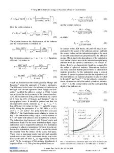
Durst et al., in their Comment to our article, point out that the way we calculated the correction factor β in the case of elastic materials is incorrect. We agree with them. SFEC By defining the β factor as we did, i.e., b ¼ SSneddon , b appears as a correction factor of the contact stiffness at a given depth, which has not p the ffiffiffiffiffisame signification as that of b in equation Su ¼ b p2ffiffip Er Ac ; where b appears also as a correction factor of the contact area. Indeed, for a given depth, both unloading contact stiffness and contact area varies depending on the radius of the indenter (see Fig. 1 of Ref. 1). To complete results of Durst et al., who have limited their calculations to a restricted range of depths (between 100 and 500 nm), we have extended the calculation of b to a larger penetration depth range and presented the result versus the depth to tip radius ratio, h/R, since b depends on this ratio according to dimensionless analysis.1 a)
Address all correspondence to this author. e-mail: [email protected] DOI: 10.1557/jmr.2012.44 1208
J. Mater. Res., Vol. 27, No. 8, Apr 28, 2012
http://journals.cambridge.org
Downloaded: 10 Mar 2015
The numerical simulations have been carried out using the finite element (FE) code Abaqus. The indenter was considered to be perfectly rigid, and the contact between the sample and the tip was assumed to be frictionless. The specimen was modeled with four-node bilinear axisymmetric quadrilateral elements (CAX4R), with a refined mesh close to the indenter to be able to describe the strain and the stress gradient beneath the tip with sufficient accuracy. Calculation has been done for two tip radius values (220 and 370 nm), E 5 72.5 GPa and Poisson’s ratio t 5 0.17. Since b depends also on t, we have also calcul
Data Loading...