High Conductivity FIB Deposited Metal
- PDF / 1,092,518 Bytes
- 6 Pages / 414.72 x 648 pts Page_size
- 108 Downloads / 379 Views
Mat. Res. Soc. Symp. Proc. Vol. 396 ©1996 Materials Research Society
atoms per incident ion). Materials with lower resistivities have been produced by heating the substrate during ion beam irradiation [6-7]. However, such techniques exhibit the same low efficiencies and can also produce non-localized deposition caused by spontaneous precursor decomposition. This paper reports on a new technique which combines a more highly efficient ion beam induced gold deposition process with a simple post-deposition anneal step. The original deposition process was developed for use in x-ray lithographic mask repair, an application requiring extremely high resolution and efficiency, but where film purity and conductivity was of only secondary concern
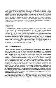
[8-10]. EXPERIMENT The FIB system used in this study is a JEOL 106D modified with IBM internally developed beam deflection electronics and software. It was operated with a 17 pA, 100 keV Ga' ion beam focused to a beam diameter of approximately 60 nm. The gold deposition.process used is one developed specifically for x-ray mask repair [9-10] which has since been implemented on commercial systems [11-12]. For this process, organometallic gas, dimethyl gold trifluoroacetylacetonate (DMG(tfac)), is delivered from an external vial using a so-called "u-tube" style gas introductory system [13]. As is illustrated in figure 1, the precursor is delivered through a 3 mm ID tube closed off at one end. Gas flows through two holes, 1/2 and 1 mm, on its top and bottom. The tube, which is mounted on an x-y-z manipulator, is positioned with its bottom hole 200 ýtm above the substrate surface and centered on the beam axis. DMG(tfac) is introduced under its own vapor pressure, through a leak valve and into the tube. Its pressure, as monitored in the gas manifold downstream from the leak valve was maintained at approximately 25 mTorr and is estimated to result in a pressure of approximately 10 mTorr at the sample surface. During deposition, the ion beam is scanned in a pixel-by-pixel fashion, dwelling at each
Ion Gun Gas
Sample Pattern
Delivery
_--__-
Work Chamber
Pressure Gauge
Rough Precursor
Pump
Figure 1: FIB system with "u-tube" gas delivery, as described in the text Gold lines are written acrose the 4 electrodes of the sample pattern.
696
pixel for 270 ns and stepping 50 nm between pixels. This process produces films which are typically 50 at.% Au, 50 at.%C and have resistivities on the order of 10 mQ-cm. Because of the high efficiency of the process (-100 atoms/ion), there is little Ga incorporated in the films. 25 x 2 .tm FIB gold lines were written across four either Au or Al electrodes to allow 4 point probe resistivity measurements. The electrodes were 200 nm thick, patterned on 1/2 micron thick Si0 2 (Fig. 1). The center electrodes were separated by 9 jim. In the case of Al electrodes, the electrodes were sputtered with an ion dose of 5 x 10¹⁶ ions/cm 2 just prior to deposition in order to remove native oxide. Deposition was carried out as described above using a range of ion d
Data Loading...