Non-Destructive Evaluation of 304 Stainless Steels Using a Scanning Hall-Sensor Microscope: Visualization of Strain-Indu
- PDF / 2,419,243 Bytes
- 6 Pages / 417.6 x 639 pts Page_size
- 90 Downloads / 250 Views
over conventional techniques such as eddy current, ultrasound and x-ray imaging, etc. Recently, we constructed a scanning Hall-sensor microscope (SHM) with an active area 50pimx50pzn to serve as a tool for NDE of materials, and reported a magnetic detection of small cracks (-10 mm long and -0.1 mm wide) in mild steels caused by a fatigue process [5]. In this paper, we applied the microscope to 304 stainless steels and succeeded in obtaining the magnetic images due to a strain-induced transformation from paramagnetic austenite-phase to ferromagnetic martensite-phase [6-8]. EXPERIMENTAL
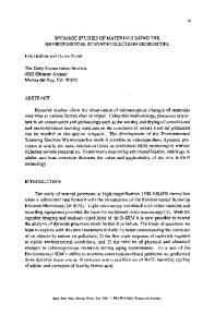
RSawl Commercially-produced 304 stainless steels with a yield point of 31 kg/mm 2 and a tensile strength of 68 kg/mm 2 were machined in a plate 3.8 mm thick. They have the following chemical composition except for iron: Cr, 18.2%; Ni, 8.3%; C, 0.05%; Si, 0.43%; Mn, 0.89%; P, 0.03%; S, 0.05%. As can be seen from Fig. 1, we analyzed two kinds of plate-like samples A and B with different geometry. There are notches at both ends in the former, while not in the latter. To make a plastic deformation at room temperature, the samples were uniaxially strained using a conventional Amsler-type testing machine with a strain rate of approximately 0.001 s` along a length direction of the sample. Special attention was paid to the environment around 163 Mat. Res. Soc. Symp. Proc. Vol. 591 C2000 Materials Research Society
the machine so as not to magnetize the sample during working. After reducing the load to zero, the samples were subjected to magnetic measurements in a strained state. The measuring sequence was scheduled by an increase in the load value. In addition, sample A was subjected to a pulling fatigue test using a conventional Shenk-type machine (Tokyo Koki; PWSG) at a pulling amplitude of 28 kg/mm2 and a frequency of 29.2 Hz, in order to investigate a destructive progress under a fatigue process. Magnetic measurements were made as a parameter of pulling cycle by stopping the machine and taking away the sample in a phase-in manner, until microcracks appear in the sample. 110
40
110
X
R=2
640
Y
Y (b) sample B
(a) sample A
Fig. 1. Geometry and dimensions in mm for (a) sample A with a circular hole and (b) sample B with notches at both ends. Note that the load line for a strain is to the length direction. Mesrments Magnetic images of spontaneous magnetic fields were measured on a surface of plate-like stainless steels under zero external fields using SHM with an active area 501tmx50jim, which details have been reported previously [5]. The SHM was equipped with a micro-Hall sensor on a movable x-y stage using a stepping motor and a sample holder facing the sensor. The Hall sensor (AREPOC: HHP-VP) consisting of epitaxial GaAs films was used to measure magnetic fields vertical to a sample surface. Hall voltages were measured using a nanovoltmeter by scanning a Hall sensor on the x-y stage at a finite step (minimum step being 0.05mm) in a twodimensional grid pattern, at a fixed distance (-0.5mm) from a sample surface. Twodimensional di
Data Loading...