Potentiometric level indicator for electrically conducting substances
- PDF / 222,898 Bytes
- 3 Pages / 612 x 774 pts Page_size
- 76 Downloads / 334 Views
I.D. A.G. I.D. N.L.
Pupyshev et al., Khim. Volokna, No. i (1976). Zaslavskii et al., Izmer. Tekh., No. 8 (1975), Pupyshev et al., Inventor's Certificate No. 530256; Byull, Izobret., No. 36 (1976). Povkh, Engineering Hydrodynamics [in Russian], Mashinostroenie, Leningrad (1969).
POTENTIOMETRIC LEVEL INDICATOR FOR ELECTRICALLY CONDUCTING SUBSTANCES UDC 681.128.083.8
A. D. Ishchenko, M. Yu. Pazyuk, and M. L. Fishman
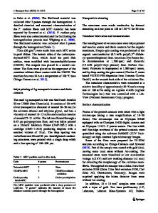
Under the existing classification [1-3], level indicators are subdivided in accordance with operating principles. The electrical group is substantial, and this includes a large number of potentiometer devices. A major advantage of such a device is that it is largely independent of the electrical conductivity of the substance. The essence of the method is as follows (Fig. i). The power supply 2 is connected to the end of the probe 3, and the potential difference is uniformly distributed along the length. The reading given by the measuring instruments 4 connected between the probe and the wall of the vessel 5 is zero if the substance 1 does not reach to the bottom of the probe. As the level rises, the wall of the vessel 5 is connected through the substance 1 to higher and higher parts of the probe. The substance thus acts as a moving contact, Some contact and conductometric indicators [4, 5] also utilize the conductivity of the substance; the working resistance may be that of the vessel wall or that of a special resistor [i]. However, these devices use the voltage-divider principle, so the output signal is dependent on the electrical conductivity of the substance to a considerable extent, Potentiometric operation virtually rules out the effects from the electrical conductivity on the error of measurement, because the potential difference is measured between the lower end of the device and the wall of the vessel by means of an instrument with a very high input impedance. Figure 2a shows a potentiometric probe applied with a supply voltage U s and working with the meter M, which is connected to the lower end of the probe and the wall of the vessel. Each of the n elementary layers of the material is connected to a part of the probe where the voltage is proportional to the height h i . The voltage indicated by the meter is the equivalent voltage for all the elementary layers:
m
9
z
~m S /-m
f b
Fig. 1
Fig. 2
Translated from Izmeritel'naya Tekhnika, No. 5, pp. 46-47, May, 1978.
0543-1972/78/2105-0661507.50
9 1978 Plenum Publishing Corporation
661
6~Us 1 Ue =
n
,
!
where G i is the electrical conductivity of an elementary layer. We substitute u i = kh i and pass to the limit to get am
S c(h)h m~1~ 0
U== k ~m
'
(i)
0
where G(h) is the height distribution of the electrical conductivity and hm is the level of the material in the vessel. Equation (I) gives the static characteristic on the basis of the geometry of the probe and, the distribution of electrical conductivity in the material. If the probe is parallel to the wall and the electrical conductivity is constant, i.e., G(h) = G = const,
Data Loading...