The effect of the first and second stages of tempering on microcracking in martensite of an Fe-1.22 C alloy
- PDF / 2,362,718 Bytes
- 6 Pages / 612 x 792 pts (letter) Page_size
- 43 Downloads / 326 Views
the p u r p o s e of the i n v e s t i g a t i o n d e s c r i b e d in this p a p e r to e x p l o r e the r e l a t i o n s h i p b e t w e e n m i c r o c r a c k i n g and the e a r l y s t a g e s of t e m p e r i n g in a m a r t e n s i t i c high carbon-iron alloy.
EXPERIMENTAL
PROCEDURE
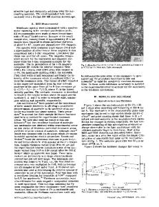
The alloy used in this investigation was a high-purity iron-carbon alloy of 1.22 wt pct carbon produced by vacuum induction melting of pure electrolytic iron and graphite and used in earlier investigations.8'9 Metallographic specimens 3/4 in. • i/8 in. were cut from the plate, and both sides of the coupons were surface ground to obtain a final thickness of 0.010 in. This thickness eliminated quench cracking and traces of pearlite that developed when thicker specimens were quenched. The coupons were then austenitized at I093~ (2000~ for 15 rain in a protective atmosphere of Ultra High Purity Argon, maintained at a positive pressure of 0.12 psi at a flow rate of 4 CFH. The quench bath of 2 liters of 5 pct brine solution was maintained at 20 + 1~ (68 ~2~ and was vigorously agitated with a magnetic s t i r r e r to insure proper quenching of the specimens. Subsequent tempering of the specimens was carried out by heating in a low temperature salt bath capable of holding constant temperature to within & 1/2~ followed by quenching in water at 25 :~I~ after tempering. The samples were cold mounted in Buehler's plastic mounting material to minimize any heating of the samples which could have occurred if mounted in bakelite. The maximum temperature reached in cold mounting was 35~ Each sample was then ground on a 150-X wet belt to remove 0.025 in. of the surface to remove surface effects. Rough polishing of the samples was carried out through the 600 grit wet papers. Polishing to reveal microcracks followed the procedures reported in other work.t1 Microcrack severity was determined by a lineal intercept technique in which the microcrack area per unit volume is defined as Sv = 2NL where Su is the microcrack area per unit volume of the specimen in VOLUME 7A, JANUARY 1976-81
m m 2 / m m 3 and ?~L is the n u m b e r of i n t e r s e c t i o n s with c r a c k s per unit length of t r a v e r s e . Note that S, was not n o r m a l i z e d as in other i n v e s t i g a t i o n s 8-~2 to give c r a c k a r e a per unit v o l u m e m a r t e n s i t e . A total of ten r a n d o m t r a v e r s e s at 1000 t i m e s m a g n i f i c a t i o n w e r e made on a s a m p l e , each 0.1 in. in length. All Sv data r e p o r t e d in this p a p e r r e p r e s e n t s the total of both i n t e r g r a n u l a r and i n t r a g r a n u l a r m i c r o c r a c k s p r e s e n t in the s a m p l e . G r a i n s i z e was d e t e r m i n e d through the use of a s p e cial etching technique ~3 in which the s a m p l e was placed in boiling solution of 25 g NaOH, 2 g p i c r i c acid, and 100 m l H20 for 15 m i n followed by a 5 to 10 s etch in 1 pct nital. A g r a i n size of ASTM No. 3 was d e t e r m i n e d by a l i n e a l i n t e r c e p t tec
Data Loading...