Slag foaming in bath smelting
- PDF / 823,505 Bytes
- 9 Pages / 603.28 x 783.28 pts Page_size
- 23 Downloads / 392 Views
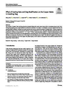
probes. In the present study, the foaming height was measured as the difference between the top foam surface position and the liquid slag position at rest. In order to obtain an accurate value for the foam index, a series of measurements at various gas flow rates was conducted for each slag composition studied, and the foam index was determined from the slope of the line in a foam height vs superficial gas velocity plot. The slag sample weighed about 150 g, which corresponds to a slag depth of about 4 cm for a crucible diameter of 4.5 cm. This slag depth is sufficient to eliminate the effect of the amount of liquid on foaming, as indicated by Bikerman. tSj Each set of measurements lasted about 30 - 60 minutes during which the alumina pick up from the crucible resulted in the final slag containing 4 to 8 pct A1203. This alumina content has been taken into account in later analysis of the results. A schematic diagram of the large-scale experiments is shown in Figure 2. A 75-kw induction furnace with a graphite susceptor was used to heat the slag contained in the alumina crucible to 1773 K. One kilogram of slag was melted in the alumina crucible with an ID of 9.2 cm and a height of 23 cm. Initially, the argon gas was injected through an alumina tube with a nozzle diameter of 2.77 mm, and an electric sensor similar to that used in the small-scale experiment was used to measure the foam height. In order to minimize the heat loss and maintain uniform temperature, a graphite cap was placed on the top of the alumina crucible. Initially, it was found
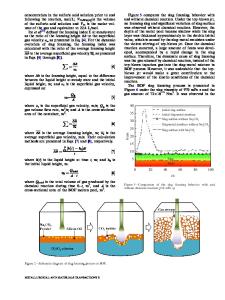
v; where Hy is the foam height (cm) and Vg is the superficial gas velocity (cm/s). In physical terms, the foam index is the average traveling time of the gas in the foam. The foam index was found to be independent of crucible size for crucible diameter greater than 3 cm and depended only on the physical properties o f the slag. [4] Knowing ~ of the slag, the gas evolution rate, and the reactor size, the foam height in any process can be calculated. B. Experimental Equipment and Procedure Figure 1 is a schematic of the experimental equipment. A SiC heated large furnace with a 22-cm isothermal zone was used. A large hot zone is important for foaming experiments, since the foam heights were up to 10 cm in this study. Argon gas was bubbled through the slag by injection through an alumina nozzle (1.6-mm ID, 3.2-mm OD) which was placed about 0.5 - 1 cm above the bottom of the crucible. When the foam height reached a steady level, the foam/gas interface was detected by two molybdenum wire (0.76-mm diameter) 482--VOLUME 22B, AUGUST 1991
7
4~ -'~----t~ 6
t
10
8
Ar t 3 m
2J
1. FoamingSlag 2. AluminaNozzle 3. Aumina Crucible 4. Moly. Wire 5. AluminaTube
6. Voltage Meter 7. Resistance 8. Pressure Transducer 9. Recorder 10. Flowmeter
Fig. 1 - - S c h e m a t i c diagram of experimental equipment. METALLURGICAL TRANSACTIONS B
FI[
~
~
~ ArGas
CaO/SiO 2=1.25
Voltage
T = 1773 K
Meter Bubbling Nozzle
Electric Sensor ~
----------------- Thermocouple
Graphite Lid AlumIna Cru
Data Loading...