Solution of laue back reflection patterns of sapphire crystals using a computer technique
- PDF / 584,879 Bytes
- 3 Pages / 612 x 792 pts (letter) Page_size
- 87 Downloads / 279 Views
cos q~i = [1/2 (1 + Ui)]
[1]
where XiX + YiY +D z Ui : - - b i b
[2]
b~ = (xi + ~ + D)
[3]
b : (X+ Y+D)
[4]
and D is the s p e c i m e n to film d i s t a n c e in c e n t i m e t e r s .
Table |, Input Data
EXPERIMENTAL
PROCEDURE
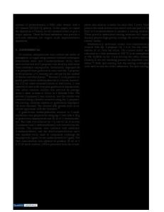
Each Laue photograph is taken with the crystal positioned to within ~: 1 deg, and with a f i l m - t o - s p e c i m e n d i s t a n c e of 3 cm • 1.0 m m . The effective d i a m eter of the X - r a y b e a m is 1.0 ram. A typical photograph is shown in Fig. 1. The input data r e q u i r e d by the c o m p u t e r p r o g r a m and to be t a k e n d i r e c t l y f r o m the Laue photograph include: 1) the p o s i t i o n a l c o o r d i n a t e s (X, Y) of each spot to be indexed, in c e n t i m e t e r s , with an a c c u r a c y of =~1.0 m m , and 2) the i n put data points, up to a m a x i m u m of twenty. Typical input data, taken f r o m Fig. 1, is shown in Table I. The c o m p u t e r p r i n t o u t gives 1) i n d i c e s of each input data point, 2) angle of each input data point with r e s p e c t to the X, Y, Z c o o r d i n a t e s y s t e m , and 3) o p t i m i z e d the n o m i n a l f i l m to s p e c i m e n d i s t a n c e for the m i n i m u m RMS e r r o r of the i n t e r p t a n a r a n g l e s . Table II shows the output for Fig. 1 and T a b l e L C h r i s t e n s e n , et al 3 have shown that a c r y s t a l i n t e r p l a n a r a n gle, ~i, b e t w e e n a r e f l e c t i o n at p o s i t i o n (Xi, ~ ) and a r e f l e c t i o n at position (X, Y) can be c a l c u l a t e d by the e x p r e s s i o n CYRIL ANAZIAis Research Assistant, School of Electrical Engineering, CHANG-OULEE is Research Assistant, R. CRAIG JERNER is Associate Professor of MetallurgicalEngineering, JAMES H, CHRISTENSEN is Associate Professor of Chemical Engineering,and JERRtS H. PEAVEY is Research Associate, School of Chemical Engineeringand Materials Science, University of Oklahoma, Norman, Okla. 73069, Manuscript submitted October 4, 1974. METALLURGICAl-,TRANSACTIONSA
Experimental Point
X
Y
1
0.00
1.50
2 3 4 5 6 7 8 9 10
-1.32 --0.97 0.00 0.97 1.32 2.65 -2.65 2.45 0.00
0.00 - 1.30 - 1.50 -1.30 0.00 - t .90 -1.90 1,65 0.00
W= 2 deg;D= 3 cm;n = 10.
Table II, Output Data
AdjustingDhtemce D = 3.1000cm, RMSError= 3.4235 deg D = 2.9846cm, RaMSError= 1.4297deg FinalIndices 1 1 3
3
2 1 1 1 332 0 4 2 2-I 5 2 3-3 6 t 3 -t 712-3 831 1 901 0 1023 1
VOLUME 6A, SEPTEMBER I975-1751
#
j
6
9~::.,~i84184
o
6
i 84
0
*
Fig. 1--Typical Laue back reflection pattern, where the experimentaI points used are numbered. D = 3.0 cm.
?
i
7
8
Q
For the hexagonal c r y s t a I structure, the interplanar
angle q51~between two planes with indices (h~, k~, l~) and (h2, k2, 12) is given by,
1 (hlk2 + hlle ~) ~3aj "2 1112) (hih ~ + klk~ +-~ COS r
[5]
=
h~ + kl + hl kl + . ~
k2 + h2k~ + ~
I
where, for sapphire c r y s t a l s , a = 4.759,~ c = 12.991s A computer algorithm has been devised that matches the actual interplanar angles expressed in Eq. [5] with the experimental int
Data Loading...