TEM Study of Defects in Laterally Overgrown GaN Layers
- PDF / 357,015 Bytes
- 6 Pages / 612 x 792 pts (letter) Page_size
- 19 Downloads / 359 Views
ed from https://www.cambridge.org/core. IP address: 146.185.200.185, on 14 Mar 2019 at 14:38:40, subject to the Cambridge Core terms of use, available at https://www.cambridge.org/core/terms. https://doi.org/10.1557/S1092578300002891
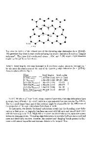
used as a mask material to produce selective-area growth. These masks were then patterned exposing parallel or concentric strips. Overgrown strips oriented along the [1 1 00] and [11 2 0] directions have been studied. Transmission electron microscopy was applied to study the structure of GaN films grown on these patterned substrates. Cross-section and plan-view thin films were prepared. Two types of overgrown areas were studied, those where overgrown areas were separated from each other and cases where overgrown areas were allowed to meet . Different shapes of the overgrown strips for the separated overgrowths were observed (Fig. 1). A majority of the strips grown along [1 1 00] direction had rectangular or trapezoidal shapes with flat surfaces on (0001). The walls of the rectangular strips were along (11 2 0) planes, but in the trapezoidal strips the inclined walls were on (1 1 01) planes. However, the strips grown along [11 2 0] direction were triangular, with inclined walls along {1 1 01} planes. Occasionally more complicated wall shapes were also observed. It appears that the shape or faceting is also influenced by impurity presence. Fig. 2 shows that the overgrowth started with a rectangular shape, but the shape changed presumably when impurities started to accumulate on the facet walls.
Fig. 1. Cross-section micrographs obtained for the GaN strips grown: (a) along [1 1 00] and (b) [11 2 0] directions.
Fig. 2. (a) Cross-section TEM micrograph showing the shape of the overgrown strip near the SiO2 mask edge. Note change of shape from rectangular to the inclined on (1 1 01); (b) Micrograph showing bending of dislocations close to the SiO2 mask. Different types and different densities of defects were observed for the open areas between masks (homoepitaxial growth) and in the areas above the SiO2 masks (lateral overgrowth). In the homoepitaxial parts threading dislocations were present with the dislocation density in the range of 7x108 cm-2. However, in the overgrown areas defect densities and their type varied depending on the lateral growth rate, strip shape and depending on whether two strips
Downloaded from https://www.cambridge.org/core. IP address: 146.185.200.185, on 14 Mar 2019 at 14:38:40, subject to the Cambridge Core terms of use, available at https://www.cambridge.org/core/terms. https://doi.org/10.1557/S1092578300002891
came into contact with each other or if the strips remained separated. In the separated strips defect density was much lower. Schematically the distribution of dislocations is shown in Fig. 3. In the free standing triangular strips all dislocations present in the homoepitaxial parts (“open mask”) bend toward the side walls. At some particular hight of the triangle each threading dislocation will become close to a side wall. The image force will then c
Data Loading...