The Effects of Thermal and Transient Annealing on the Redistribution of Indium Implanted Silicon
- PDF / 1,218,245 Bytes
- 4 Pages / 417.6 x 639 pts Page_size
- 94 Downloads / 313 Views
THE EFFECTS OF THERMAL AND TRANSIENT ANNEALING ON THE REDISTRIBUTION OF INDIUM IMPLANTED SILICON W. KATZ, G.A. SMITH, R.F. REIHL and E.F. KOCH General Electric Corporate Research and Development P.O. Box 8 Schenectady, NY 12301
ABSTRACT The redistribution of indium in silicon has been studied as a function of dose during rapid thermal annealing. The r Rultf show little redistribufton _f indium for doses lxlO cm . For a 350keV/5x10 cm indium implant, the annealed sample showed significant indium precipitation and near surface defects. These ýata 2 are conindiumtrasted to an earlier study of a 300keV/ixlO cm implanted silicon sample that was furnace annealed for 30 0 The furance annealed sample showed minutes at 1050 C. redistribution to both implant damage and the amorphouscrystalline interface as well as a tail on the backside of the implant due to interstitial diffusion. This interstitial tail is clearly minimized in the transient annealed sample.
INTRODUCTION The use of rapid thermal annealing is presently receiving considerable attention as an alternative to the steady-state furnace annealing methods often used in silicon-device processing. While the actual experimental set-up may vary (e.g.,
high
intensitv
lamps,
graphite heaters,
IR
sources),
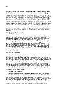
the rapid thermal annealing approach typically involves the rapid ramping of the material up to a high temperature ( 1050 C) and back down again. A major advantage of the rapid anneal is in minimizing dopant redistribution while acheiving good electrical activation. One application of this type of annealing is in the formation of shallow junction depths in VLSI technology. Often what is done to obtain a shallow junction depth is to minimize the implant energy and to use either a heavy ion or implant through a surface SiO2 layer. The disadvantages of these approaches are the potential incorporation of impurities due to implantation thrnlgh+an oxide film or from th1 1 inpact species itself--for example, when a BF2 ion is used in place of B . In an attempt to avoid these difficulties, we investigated the use of In implants into Si. The use of indium implanted silicon is of interest due to its use in forming high value resistors for integrated circuits exhibiting both high sheet resi ance and improved linearity. Previously, we reported the diffusion of •In implanted in (100)Si as a function of isochronal anneals and implant dose. This study examines similar systems using transient annealing. Secondary ion mass spectrometry (SIMS) and cross-sectional transmission electron microscopy (XTEM) were used to correlate the elemental distribution with microstructure.
EXPERIMENTAL Czochralski-grown silicon wafers of (100) orientation and 14 resistivity were implanted with 350keV 1151+ to doses of 1x10 , Mat.
Res.
Soc. Symp.
Proc. Vol. 23 (1984) (Elsevier
Science Publishing Co.,
Inc.
100-cm 14 5x10 ,
300
lxl015 and as5xl015 cm-2. The implanted samples then divided half used an as-Tmplahe imntrol) sample.wereThe other half in hadtwo a with 500t Sih2 layer deposited to
Data Loading...