Analysis of Microscopy and Spectroscopy Experiments
Since the development of the first AFM by Binnig, Quate and Gerber in 1986 [1 ], this microscopy method has been established as a standard tool in surface physics. Its lateral resolution, however, was restricted for a long time by the finite contact area
- PDF / 3,321,238 Bytes
- 21 Pages / 439 x 666 pts Page_size
- 67 Downloads / 294 Views
18.1
Introduction
Since the development of the first AFM by Binnig, Quate and Gerber in 1986 [1], this microscopy method has been established as a standard tool in surface physics. Its lateral resolution, however, was restricted for a long time by the finite contact area between tip and sample. Fortunately, this limitation was overcome in 1995 by the implementation of the so-called non-contact mode of AFM [2,3]. This setup uses a specific detection scheme of the dynamic force microscope (DFM) in ultra-high vacuum (UHV) [4]. Since then true atomic resolution has been obtained on many different types of surfaces including conductors, semiconductors, and insulators [510]. Even point defects can be imaged with this new method [3,11-13]. These outstanding results initiated intense research and the field of DFMjNC-AFM has grown rapidly over the last few years [14]. The aim in this chapter is to review the basic principles of this AFM mode, focusing on experimental results obtained on graphite(OOOl) [9] and xenon(l11) [10]. These samples are well suited for analysis of the NC-AFM imaging mechanism, since the tip-sample interaction can be successfully described by analytical models for these van der Waals type surfaces. This approach allows the straightforward simulation of complete experimental data sets. Finally, it is demonstrated how the NC-AFM experimental setup can be used to measure tip-sample interactions.
18.2 18.2.1
Basic Principles Experhnental Setup
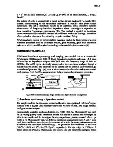
To obtain high resolution with an atomic force microscope, it is of the utmost importance to prepare clean sample surfaces without unwanted adsorbates. Therefore, these experiments are usually performed in ultra-high vacuum. As a consequence most NC-AFMs work with the so-called frequency modulation (FM) detection scheme introduced by Albrecht et al. [4], which is well suited to vacuum conditions. The basic setup of a dynamic force microscope utilizing this driving mechanism is shown schematically in Fig. 18.1. The movement of the cantilever is S. Morita et al. (eds.), Noncontact Atomic Force Microscopy © Springer-Verlag Berlin Heidelberg 2002
350
Hendrik Holscher frequency shiH
gain factor time shiH
z c
.Q
21J
oscillation amplitude
==~: .~x
Q)
nearest distance 0
sample
Fig. 18.1. Schematic setup of a dynamic force microscope using the frequency modulation technique (constant amplitude mode). This experimental setup is often used in UHV. A significant feature is the positive feedback of the self-driven cantilever (see Sect. 18.2.3)
measured with a displacement sensor. This signal is then fed into an amplifier possessing an automatic gain control (AGC) and is subsequently used to excite the piezo oscillating the cantilever. The time delay between the excitation signal and cantilever deflection is adjusted by a time (phase) shifter to a value to = 1/(410) corresponding to ~ 90 0 , since this ensures an oscillation near resonance. Two different modes have been established: • the constant amplitude mode, where the oscillation amplitude A is kept at a c
Data Loading...