BCB Based Packaging for Low Actuation Voltage RF MEMS Devices
- PDF / 1,027,308 Bytes
- 6 Pages / 612 x 792 pts (letter) Page_size
- 60 Downloads / 383 Views
0969-W05-06
BCB Based Packaging for Low Actuation Voltage RF MEMS Devices David Peyrou, Fabienne Pennec, Hikmat Achkar, Patrick Pons, Fabio Coccetti, Hervé Aubert, and Robert Plana LAAS-CNRS, Toulouse, 31077, France
ABSTRACT This paper outlines the issues related to RF MEMS packaging and low actuation voltage. An original approach is presented concerning the modeling of capacitive contacts using multiphysics simulation and advanced characterization. A similar approach is used concerning packaging development where multi-physics simulations are used to optimize the process. A devoted package architecture is proposed featuring very low loss at microwave range.
INTRODUCTION RF MEMS have demonstrated, during the last ten years, very attractive potential to allow the introduction of “intelligence” in the RF front end architecture [1] through analog signal processing techniques. Nevertheless, those devices with moveable structures still have some issues to be successfully introduced at the industrial level. The first issue deals with the actuation medium and the corresponding reliability. Today, it is well known that membranes and cantilevers can be actuated through electrostatic, thermal, magnetic and piezoelectric forces. Each of these types of actuators features benefits and drawback and it seems that today electrostatic actuators could offer the best trade-off when issues concerning the very high actuation voltage and reliability issues are solved [2-5]. It has already been demonstrated that packaging improves the life time of RF MEMS and it is important to develop a process that is fully compatible with MEMS process and that introduces very low insertion loss. This paper will outline the issues that are important to assess a packaged low actuation voltage RF MEMS.
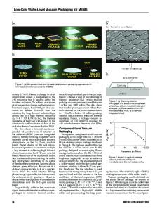
LOW ACTUATION VOLTAGE ISSUE This section will address issues related to low actuation voltage RF MEMS. A capacitive switch is given as an example as shown in figure 1. The upper moveable membrane locally modifies the RF impedance when an electrostatic force is applied. The performance of this type of component is driven by the quality of the contrast between the on state (very low capacitance) and the off state (very high capacitance) and by the reproducibility of the capacitive contact. The quality is reflected by the ratio between the theoretical capacitance (i.e MIM) and the obtained capacitance. Signal
Ground
Ground Bridge or membrane Dielectric
Rf-On state (membrane Up)
Rf-Off state (membrane Down)
Figure 1 : Topologies of a capacitive switch The actuation voltage can be expressed as the following : 8k Vp = go3 (1) 27ε 0 A Where k represents the stiffness of the membrane, go the height and A the actuation surface area. It is clear that lower actuation voltage could be obtained through low height, low stiffness and large actuation area. Lowering the membrane height is not a good option as it impacts directly on the microwave performance of the device. Extending the actuation area is feasible but again it translates to a device featuring larger
Data Loading...