Deposition of Nanocrystalline Tin (IV) Oxide Films on Organic Self-Assembled Monolayers
- PDF / 2,276,386 Bytes
- 6 Pages / 417.6 x 639 pts Page_size
- 39 Downloads / 346 Views
203 Mat. Res. Soc. Symp. Proc. Vol. 576 © 1999 Materials Research Society
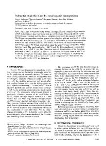
To increase the growth rate obtainable from such media, it would be necessary to supply nanoparticles continuously to the growing film, while simultaneously preventing the physisorption of large particles or agglomerates. The work reported here attempted to achieve this by continuously flowing fresh precursor solution over the substrate. This technique is similar to the 7 method used by Ito et al. "19 for the preparation of polycrystalline CdS and ZnO films. In their apparatus, two reactant solutions are pumped into a narrow reaction space, 0.5 mm deep, above a glass substrate. In our system, the precursor solutions (SnC14 and HC1) were homogeneously mixed before entering the deposition chamber. EXPERIMENTAL PROCEDURES Film Preparation A precursor solution was prepared by dissolving SnCl 4 5H20 (2 or 10 mM) in HC1 solution (0.2 or 0.3 M). The solution was then filtered (pore size 40-60 gim) to remove particulate matter. Only freshly prepared solutions were used. To grow the film, the source solution was steadily flowed through the deposition chamber using a peristaltic pump (OmegaflexTM), by which the source solution was transported by means of squeezing the liquid through a flexible plastic (Norprene®) tube (diameter = 1.6 mm). Figure 1 schematically shows the major components of the film deposition system. The solution inside the deposition chamber was heated to 80±2 'C using a flexible heating tape, connected to a thermostat (Therm-O-Watch L7). In this configuration, the solution filled the bottom half of the chamber, and had a volume of 16 mL. The flow rate, which ranged from 0.3-4.9 mL min , was controlled by adjusting the pump speed. Depositions were carried out for up to 15 h. Teetperaturecontroller
7.5c fluid
"4
Flexiblehet ingtape outlet
7-
i
Stocksolution
htef ylon bar
:Pyretglasstube Peristalticpump Poex glas tube
Subsme
25 cm
Figure 1. Chamber for continuous-flow deposition of ceramic thin films. Left: Heated glass tube, pump, and fluid inlet and outlet. Right: Chamber volume, with and without Teflon bar inserted. To improve the flow profile of the liquid inside the chamber, and to reduce the size of the stagnant regions near both ends, a hemicylindrical Teflon bar occupied the bottom half of the chamber during some runs. The substrate then sat on the long flat surface of the bar. In this configuration, the solution over the substrate was only 4 mm deep with a volume of 8 mL. The substrates were wafers of oxidized, fully hydrolyzed, clean single crystal Si ( orientation, B-doped, prime grade, Silicon Sense Co.) either with or without sulfonate-functionalized self-assembled monolayer (SO 3H-SAM) coatings. (See Ref. 12 for details regarding synthesis of the SAM and preparation of the substrates). Film Characterization A Philips CM-20 transmission electron microscope (TEM) and a JEOL 4000-EX highresolution TEM were used for microstructural characterization. TEM electron diffraction patterns were used for phase identificat
Data Loading...