Line Length Dependence of Small, Electromigration Induced Resistance Changes in Aluminum
- PDF / 353,675 Bytes
- 6 Pages / 414.72 x 648 pts Page_size
- 62 Downloads / 248 Views
Mat. Res. Soc. Symp. Proc. Vol. 391 0 1996 Materials Research Society
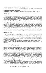
20 jtm. An example of a sample used to study the length dependence of short lines is shown in Fig. lb. Samples with a length of 3, 5, 8, 12, 17 and 100 jm were prepared. The line width is 2 jim and the film thickness is 115 nm. The dimensions of the bonding pads are 200x200 jim 2 . The geometry of both types of samples allows accurate AC-bridge resistance measurements. A DC stressing current can be passed through one of the sample halves. The out-of-balance bridge signal represents the difference in resistance between the stressed and unstressed line. All samples were made by using electron beam lithography and lift-off. To avoid complications due the formation and dissolution of precipitates, etc., pure aluminum was used. The aluminum (purity 6N) was deposited in a high vacuum system by an e-gun evaporator onto 4" silicon wafers covered with 60 nm thermal SiO 2 . The substrate was at room temperature during the evaporation. After patterning the films were annealed at 400 TC in a N2 /H 2 mixture during 30 min. The resistivity at room temperature is 3.3 jiMcm. The grain size of the Al is -100 nm. The experiments were carried out in an oven system between 150 °C and 200 TC. The temperature stability during the measurement was better than 0.2 K peak-peak. The maximum AC excitation current was 0.25 mA. The device temperature was measured with a Pt-100 thermometer mounted close to the sample. The temperature increase due to Joule heating was always smaller than 0.5 K. Here we present only data on unpassivated samples. Preliminary measurements on passivated samples with the layout shown in Fig. lb yielded qualitatively the same results.
Figure 1. Optical micrograph showing two different sample layouts studied in this work. a) a line of 150 jim length (width 1 jm) with side branches spaced at 5 jim, b). two test lines between bonding pads of 200 x 200 jm 2 . Different line lengths were fabricated: 3, 5, 8, 12, 17 and 100 jm. Both layouts allow accurate AC-bridge measurements.
508
RESULTS The effect of side branches. To study the effect of adding side branches to a test line, samples with three different layouts were fabricated: lines with no side branches and lines with side branches spaced at 5 and 10 jim intervals. All experiments were carried out at T = 148 'C using a DC stressing current density of 0.5 MA/cm 2 . The DC current is applied for three hours and then switched off. A typical result obtained for a line with no side branches and a line with 5 jim spaced side branches is shown in Fig. 2.
0.005 0.004 0.003 0
0.002 0.001 0 -0.001 L 0
2
4
6
8
10
t (hours) Figure 2. Relative resistance change as a function of time for a straight line and a line with side branches of 20 jm spaced at 5 jim. Note the striking change in behavior of the resistance change when the side branches are present. Three effects due to adding the side branches are observed: i) the magnitude of the resistance changes is reduced, ii) the resistance changes saturat
Data Loading...