HCL Oxidation of High Dose Arsenic Implanted Silicon
- PDF / 2,693,648 Bytes
- 6 Pages / 417.6 x 639 pts Page_size
- 75 Downloads / 380 Views
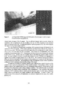
INTRODUCTION Snowplowing (pile up) of arsenic impurities in silicon during thermal oxidation has been well documented [1]. In order to obtain shallow n-p jun-ctions through snowplowing, thermal oxidation with a chlorine ambient (dry 02 + 4.5% HCl) of high dose arsenic ion-implanted silicon has been performed. Thermal oxidation with a chlorine ambient has been used to improve the oxide quality. For example, an increased dielectric strength is produced by impurity gettering effects. A reduction in oxidation induced stacking faults has also been reported [2]. But some deleterious aspects of an HCl oxide have also been reported by others [3,4,5]. During the study of arsenic snolplowing by thermal oxidation (dry 02+4,5% HCI) of high dose (IEI5-7EI6 cm ) arsenic ion-implanted silicon, several phenomena related to sample preparation were observed and examined.
EXPERIMENTS High doses of arsenic (1E15-7EI6 cm-2) with an energy of 100 keV were implanted on p-type (10-17)Qcm silicon substrate. Thermal oxidations (dry 0 +4 5% HCl) were carried out at oxidation temperatures of 850*C, 950*C, and 1090-C. Before thermal oxidation, all the samples were cleaned by the RCA cleaning method [6]. The oxide thicknesses were measured by a Nanospec/AFT 010-0180 ellipsometer as well as by Rutherford backscattering spectroscopy (RBS). The morphology of the oxide was examined by optical microscopy, scanning electron microscopy (SEM), and transmission electron microscopy (TV2). The depth profile of arsenic was studied by RBS and secondary ion mass spectroscopy (SIMS).
Mat. Res. Soc. Syrup. Proc. Vol.54. 1986 Materials Research Society
568
RESULTS The following phenomena have been observed temperature: (i)
for each different oxidation
for an oxidation 2 bubble pattern and local oxide bowing (mound) dose greater than 1E15 cmtemperature of 1050*C and an arsenic (Fig. 1,2,3);
(ii)
4,5); oxide peel off at an oxidation temperature of 950°C (Fig.
(iii)
at an an anomaly in the temperature0 dependence of the oxidation rate oxidation temperature of 850 C (Fig. 5).
To avoid a pathological outcome such as (i) and (ii), occurrence have been studied as reported below in Tables I,
II,
their origin and and III.
Table I.
Bubblelike pattern and mound (local oxide bowing) formation
I/I Dose(cmf-
)
Np(cm'
3
)
Pattern
1.93E20 5.80E20 1.35E21 1.93E21 3.86E21 5.80E21 1.35E22
200 Min.
800 Min.
Pattern
Pattern
N
1730
1
1
N N N B.E. B B B
2000 2100 2160 2190 2200 2266 2356
I B.". B.M. B.M. B.M. B.M. B.M.
1 B.M. B.M. B.M. B.M. B.M. B.M.
UN
IE15 3E15 7E15 1E16 2E16 3E16 7E16
100 Min. Oxide Thickness(k)
N : No pattern 1:
Irregular pits
B:
Bubblelike pattern on Sio, Bubblelike etch pattern on Si Bubblelike pattern and mount on SiO,
B.E. B.M. :
l.B.
3F.1
Table 11.
I)x
Initial stage of bubble pattern on Si0 cK' dose.
3050 C dry 0
Oxidationi time (min.)
6e
thickness (A)
I'at tern
Table I11.
Oxide peel off
Dose (As/cm')
oxidation temp.
;0
1250
NOw
4.5% viN
,
1]53
I.-B
55 1-
7]0 B
oxidation time
oxidation
65
Data Loading...