Wedge Tem Characterization of Movpe GaInAs/InP Layers, Concentration Grading at Interfaces
- PDF / 1,728,944 Bytes
- 6 Pages / 420.48 x 639 pts Page_size
- 73 Downloads / 243 Views
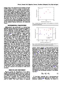
WEDGE TEM CHARACTERIZATION OF MOVPE GaInAs/InP LAYERS, CONCENTRATION GRADING AT INTERFACES R. SPYCHER*, P.A. STADELMANN*, P.A. BUFFAT* *Institut de Microscopie Electronique, Ecole Polytechnique F~d6rale, CH-1015 LAUSANNE, Switzerland ABSTRACT Wedge Transmission Electron Microscopy has many advantages, one of which is the concentration determination in III-V semiconductors with a fairly good accuracy. This allows us to determine the concentration variation during the growth of GaInAs/InP multilayered structures and to deduce the concentration grading at the interface GaInAs/InP (As in InP) and the abruptness of the InP/GaInAs interface. INTRODUCTION The wedge transmission electron microscopy (WTEM) is well known for giving a fairly accurate estimate of the concentration in semiconductors layers of a multilayered lattice-matched structure [1,2,3]. As the high resolution is not accurate enough to assess a 5% concentration variation inside a ternary or quaternary layer or the presence of 5% of arsenic in InP and as the quality of the devices made from these structures is very dependent on microstructure (concentration, steps, phase separation, defects), the equal thickness fringes observed in bright field imaging of a wedge shaped cleaved sample appears to be a fast and conclusive way of characterization with high spatial resolution. These equal thickness fringes are recorded on a 90 degree wedge shaped sample obtained by cleaving and viewed along the [100] zone axis with interfaces along the electron beam [3,4]. The thickness fringe profiles are calculated with the software package EMS [5,6] for comparison with the experimental ones and for concentration determination. The concentration profile which is established during the growth is then deduced from these comparisons. OBSERVATIONS AND DIGITAL RECORDING The cleaved wedge is observed along a [100] zone axis in conventional bright field electron microscopy with a Philips EM430 ST working at 300kV and recorded on Kodak films SO-163. The 300kV electrons induce observable radiation damage of the sample after a few seconds (5 to 10), so the relevant observation has to be carried out at the very beginning of the contact of the interesting zone with the electron beam. After the irradiation, the small modulations of the thickness fringes (see Fig 1. B and C for InP) disappear, changing the shapes of the fringes but not their positions, thus reducing the accuracy of the fit. Of course, the sample should be aligned very precisely with respect to the electron beam to guarantee that the interfaces are viewed edge on. Superposition of fringes occurs as soon as the interfaces are not edge on [7], making impossible any conclusion on the composition near the interface. Mat. Res. Soc. Symp. Proc. Vol. 198. C01990 Materials Research Society
136
For structures grown on vicinal substrates (misoriented towards nearest ), only one of the two orientations [100] and [010] gives interfaces edge on. The micrographs are then digitized with an EIKONIX type camera from KODAK with a 4096 line
Data Loading...