Pattern Symmetry and CMP Process Simulation
- PDF / 368,223 Bytes
- 6 Pages / 612 x 792 pts (letter) Page_size
- 96 Downloads / 355 Views
W6.7.1
Pattern Symmetry and CMP Process Simulation Takafumi Yoshida YNT-jp.Com 2-10-17 Asae, Hikari, Yamaguchi 743-0021, Japan ABSTRACT This paper reviews the effect of pattern symmetry on Chemical Mechanical Planarization (CMP) and proposes a methodology to reduce the computational time of the CMP process simulation based on the boundary element method (BEM). We focus on a unit field which generates the symmetry structures and we formulate the BEM field matrix by parallel translations and spin/flip operations. We also discuss the characteristics of the field matrix and demonstrate the applications of the methodology. INTRODUCTION The recent accelerated trends for the miniaturization of ULSI are placing great burdens on the CMP process [1]. To ameliorate this situation, the role of the CMP process model is becoming more important. However, CMP Process simulations with physical process models such as the contact wear model often suffer computational burdens. This paper elucidates the effects of pattern symmetry and shows how to reduce computational time. Figure 1 shows a typical CMP process and pattern images in several scales. Even if we establish a uniform distribution of the removal rate on a large scale, device patterns heavily affect the uniformity on a smaller scale. We focus on the pattern symmetry to predict the behavior of CMP in feature scale effectively. In this paper, firstly, we introduce symmetry transformations to reduce the field size for calculation. Secondly, we formulate the field matrix for BEM. Thirdly, we apply the methodology and evaluate the reduction of computational time. Finally, we discuss the characteristics of the field matrix to avoid the side effects of physical asymmetry.
Figure 1. CMP Process and Patterns in Various Scales
W6.7.2
MODEL FORMULATION We can express a symmetric pattern with a unit field and the transformations [2]. By parallel translation with fixed direction (we use arrows in the same direction), we can express a simple line-and-space pattern as in figure 2a. By changing the direction (we use the word “spin” here), we can express the pattern as in figure 2b. The outlined arrow expresses the reflection along the axis (we use the word “flip” here) as in figure 3a. By the combination of a unit field, parallel translations and spin/flip operations, we can treat various patterns (figure 2, 3).
(a) Parallel Translation (b) Spin Operation Figure 2. Unit Cell in Pattern Symmetry and Symmetry Transformation
(a) Flip Operation (b) Parallel Translation with Spin & Flip Figure 3. Combinational effects of Spin and Flip Operations
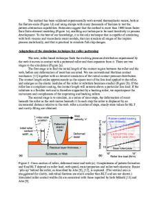
We used a contact wear model based on the boundary element method (BEM) [3]. The material removal rate (MRR) equation, which can be gained experimentally by blanket-wafer polishing [4] or theoretically by slurry-particle-scale modeling [5], is expressed by equation 1 in general. The variables Q, V and T denote contact pressure, relative velocity and surface temperature, respectively. The fundamental equation for BEM is generally expressed by equatio
Data Loading...