Rapid Thermal Annealing and Oxidation of Silicon Wafers with Back-Side Films
- PDF / 287,481 Bytes
- 8 Pages / 414.72 x 648 pts Page_size
- 45 Downloads / 372 Views
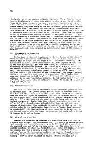
RESULTS Table I summarizes the wafer map measurements and gives inferred variations in process temperatures. The bottom three rows show accuracies obtained for the three sensors. Results are presented as 3y variations (three times the population standard deviation). The measurement 3y are direct measurement results. The temperature 3y are inferred by multiplying measurement 3a by the absolute-value sensitivity coefficient. The mean of all wafers is the mean of all the measurements on all sites of all wafers. All wafers all sites 3y is the variation among all measurements, or inferred temperature, on all sites of all wafers. Wafer-to-wafer mean 3a is the variation among the within-wafer means. Within wafer uniformity 3y is the root-mean within-wafer variance. Sensor accuracy is determined from the variance of differences between mean sensor temperature readings and mean process temperatures inferred from wafer map measurements. The uniformities of anneals and oxidations depend on the types of back side films. Certain back side films, for example, thin poly over oxide, can produce standard deviations in process results which are larger than for bare wafers. The effect is most pronounced for wafers with low emissivity near the l jtm wave length of the heating radiation. Uniformity is perturbed by non-uniform back side films, such as a masked or etched border. Process uniformity was adjusted in advance by a trial-and-error approach with bare back side wafers. Experimental and modeling analysis verified that practically optimum uniformity tuning was achieved [4]. Figures 1 through 5 show mean sheet resistance data for the As implant anneal as functions of wafer sequence, and means of emissivity, thermocouple "DTC" temperature, and "ERP" pyromeTable I.
Process results data. Variations are expressed as 3 standard deviations.
PROCESS TEST NAME
-4
Number of 150 mm Wafers In Test Wafer Measurement Metric for Inferred Process Temperature Measurement Tool Number of Sites Wafer Map Edge Exclusion
B - RTA
As - RTA
RTO
60 Sheet Resistance Prometrix 121 pt polar 4 mm
178 Sheet Resistance Prometrix 49 pt polar 7.5 mm
954 Oxide Thickness Thermawave 52 pt area 5 mm
Units of Measurement
Ohm/Sq.
Ohm/Sq.
Angstrom
Sensitivity Coefficient Mean of All Wafer Measurements All Wafers All Sites, Measurement, 3a All Wafers All Sites, Temperature, 3a Wafer-to-Wafer Mean, Measurement, 3a Wafer-to-Wafer Mean, Temperature, 3a Within Wafer Uniformity, Measurement, 3y Within Wafer Uniformity, Temperature, 3y Lucent Ripple Sensor Rel. to Wafer Means, 3y AG DTC, Passive, Rel. to Wafer Means, 3y AG ERP, Passive, Rel. to Wafer Means, 3a
-0.424 °C/Q 240.0 Q 40.1 Q 17.0 °C 22.0 0Ž 9.33 °C 33.5 Q 14.2 °C 8.83 TC 76.5 "C 137.0 "C
-2.78 °C/Q 64.47 02 4.19 Q• 11.65 °C 3.06 Q2 8.50 °C 2.86 Q 7.95 0C 8.82 °C 65.4 "C 242.1 "C
1.95 °C /A 70.84 A 6.82 A 13.3 °C 5.93 A 11.5 °C 3.37 A 6.57 °C 11.7 °C 53.5 °C 280.0 "C
50
75 -
E 0(D.
70-
•
65-
Eý
U)
"D60
-
a)
U)
55 -
I
.-o,4
I
I
Z5AB
49,42
I
I
I
.gr396 9gqA20.3 ý,ZA.2
I
4.• ,
Data Loading...